Isuzu N-Series. Service manual - part 266


  Index      Isuzu     Isuzu N-Series - service and repair manual


Search            


Content   ..  264  265  266  267   ..


Isuzu N-Series. Service manual - part 266


5A4-38 ABS/ASR

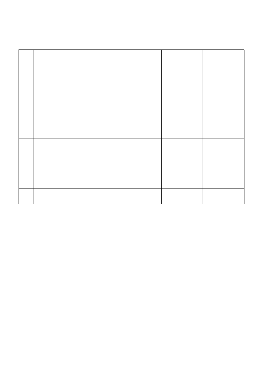
DTC:C0213 (Flash Code 13) Model Type Identification Fault Due to Wrong Assembly of
Control Unit

Step

Action

Value

YES

NO

1

1. Turn the starter switch OFF.
2. Disconnect the J-177 connector of the

EHCU.

3. Turn the starter switch ON.

Measure the voltage between the J-177 con-
nector terminal 18 and the 1,23.

Is the voltage within the specified value?

0.5 — 4.5V

Go to Step2

Go to Step3

2

Repair the short circuit and improper connec-
tion in J-177 connector terminal 18.

Measure the voltage between the J-177 con-
nector terminal 18 and 1,23.

Is the voltage within the specified value?

0.5 — 4.5V

Go to Step3

Go to Step4

3

1. Install all the components, and check that

those are installed properly.

2. Clear the DTC.
3. With Tech 2:

• Connect the J-177 connector of the

EHCU. 
Check the model type code.

Is this step completed?

Go to “Diagnostic 

basic flow”.

Go to Step4

4

Replace the EHCU with a new one.

Is this step completed?

Go to “Diagnostic 

basic flow”.

Go to Step3

ABS/ASR 5A4-39

Model Type Identification by Control Unit

EHCU (ABS control unit) is exclusively installed for each
vehicle type, based the drive system, brake type, tire,
etc. Also, you can use the warning lamp blinking pattern
to identify the type of control unit (for which vehicle
type).

How to Indicate Model Type Identification Re-
sult

With the ignition switch OFF, short the terminal 12 with
the terminal 4 or 5 (ground) of the self-diagnosis con-
nector, and depress the brake pedal and then turn the
starter switch to ON. The ABS warning lamp will blink to
indicate the result.

1.2

1.2

1.2

0.4

0.4

0.4

ON

OFF

ON

OFF

ON

OFF

OPEN

 GND

Ignition switch

Diagnosis connector

Brake switch

Warning lamp
(Raised floor model)

Unit: sec

Approx.

3.2 sec

Vehicle model identification code: 1

0.4

N5A2036E

Model type 

identification 

code

2WD ABS

1

Raised floor model with front 

wheel disc brake

2

Flat low model with front wheel 

disc brake

3

Raised floor model with four 

wheel drum brake

7

NQR model for EC

8

NQR model for Australia

5A4-40 ABS/ASR

DTC:C0214 (Flash Code 14) EHCU Fault

Check flow B-3

Step

Action

Value

YES

NO

1

1. Turn the starter switch OFF.
2. Disconnect the connector of the EHCU.
3. Check for continuity between the J-177

connector terminal 1,23 and the body
ground.

Is there continuity?

Go to Step2

Go to Step3

2

1. Connect the connector of the EHCU.
2. Clear the DTC.
3. Perform the self-diagnosis after turning

the starter switch from OFF to ON.

Is DTC displayed repeatedly?

Go to Step4

Go to Step5

3

Repair the circuit for open/short circuit, and
the connector for improper connection.

Is this step completed?

Go to Step5

4

Replace the EHCU.

Is this step completed?

Go to Step5

5

1. Install all the components, and check that

those are installed properly.

2. Clear the DTC.

Is this step completed?

Go to “Diagnostic 

basic flow”.

Go to Step5

ABS/ASR 5A4-41

DTC:C0215 (Flash Code 15) ECU Power Supply Fault

Check flow B-4

Step

Action

Value

YES

NO

1

Is the battery voltage normal?

Go to Step2

Go to Step5

2

1. Turn the starter switch OFF.
2. Disconnect the connector of the EHCU.
3. Start the engine.
4. Measure the voltage between the J-177

connector terminal 2 and the J-177 con-
nector terminal 1,23.

Is the value within specified value?

17 — 33.5V

Go to Step3

Go to Step6

3

Look for the circuit with improper connection.

Is improper connection found?

Go to Step4

Go to Step8

4

Repair and perform the self-diagnosis.

Is DTC displayed repeatedly?

Go to Step7

Go to Step8

5

Charge or replace the battery.

Is this step completed?

Go to Step8

6

Repair the circuit for open/short circuit, and
the connector for improper connection
between the J-177 connector terminal 2 and
the fusible link FL-9.

Is this step completed?

Go to Step8

7

Replace the control unit.

Is this step completed?

Go to Step8

8

1. Install all the components, and check that

those are installed properly.

2. Clear the DTC.

Is this step completed?

Go to “Diagnostic 

basic flow”.

Go to Step8


Content   ..  264  265  266  267   ..