Isuzu N-Series. Service manual - part 256
 

  Index      Isuzu     Isuzu N-Series - service and repair manual


Search            


Content   ..  254  255  256  257   ..


Isuzu N-Series. Service manual - part 256


EXHAUST BRAKE 5E-5

UNIT REPAIR

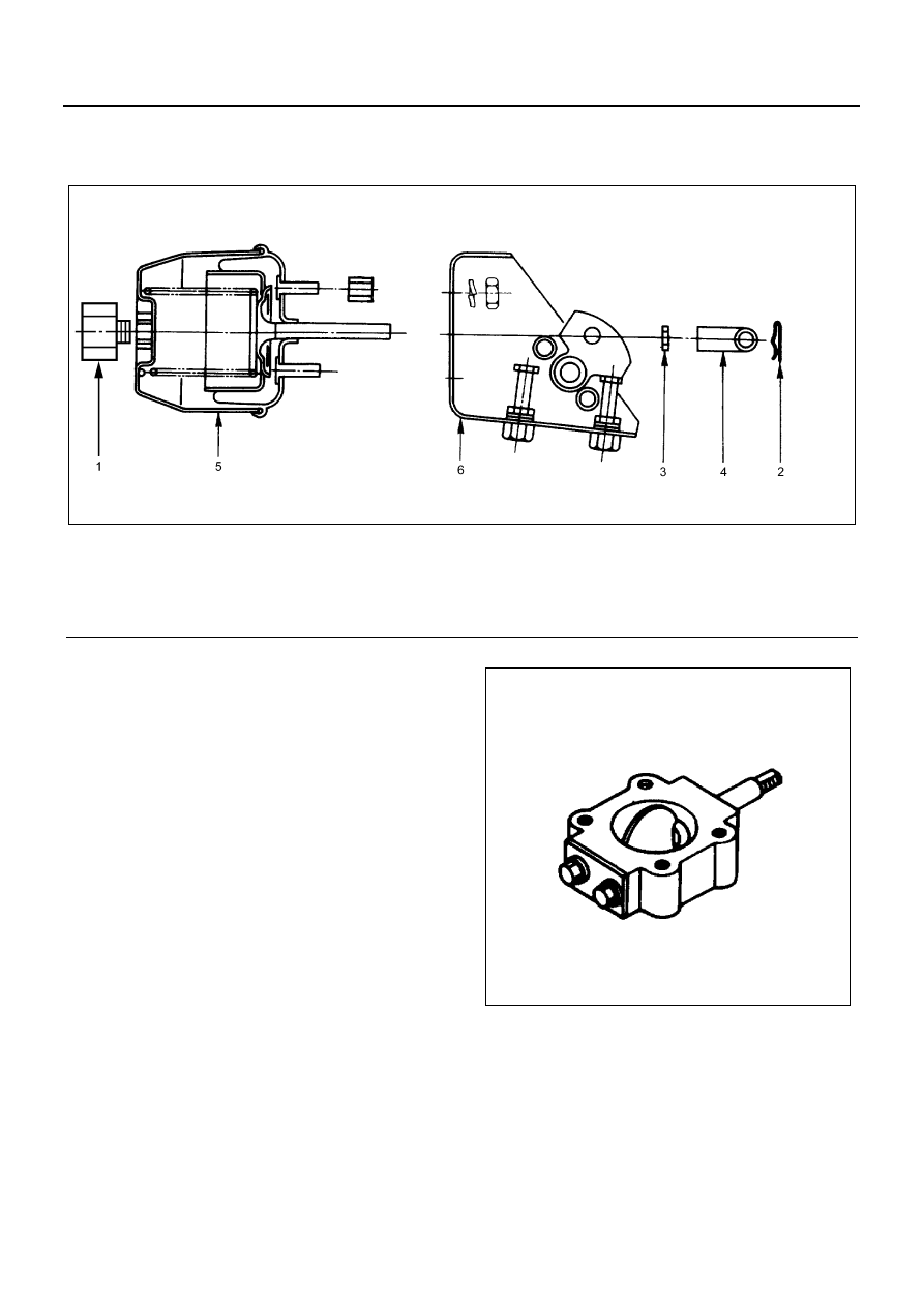
Exhaust Brake Unit

Disassembly

1. Exhaust Brake Valve Connector
2. Cotter Pin
3. Lock Nut
4. Clevis Joint
5. Power Chamber
6. Exhaust Valve Assembly

Inspection and Repair

Make the necessary adjustments, repairs, and part re-
placements if excessive wear or damage is discovered
during inspection.
Visual Inspection
Visually inspect the following parts for excessive wear
and damage.
If excessive wear or damage is discovered during in-
spection, the part(s) must be replaced.

• Exhaust brake valve
• Exhaust brake shaft
• Butterfly valve
• Bushings
• Power chamber

Power Chamber
(1) The exhaust brake valve should operate smoothly
when the negative pressure (400 mmHg to 700 mmHg)
is applied to the power chamber via the vacuum pump.

Legend

1. Exhaust brake valve connector

4. Clevis joint

2. Cotter pin

5. Power chamber

3. Lock nut

6. Exhaust valve assembly

N5A0466E

N5A0375E

5E-6 EXHAUST BRAKE

(2) At the points (A) and (B), the average clearance be-
tween the valve and the vehicle body should be as men-
tioned in the following table when the negative pressure
(650 mmHg to 700 mmHg) is applied to the power
chamber via the vacuum pump.

Reassembly

1. Exhaust Valve Assembly
2. Power Chamber

Tighten:
Power chamber fixing nut to 14 N

⋅m (1.4 kg⋅m / 122 lb⋅in)

3. Lock Nut

Tighten:
Lock nut to 13 N

⋅m (1.3 kg⋅m / 113 lb⋅in)

4. Clevis Joint
5. Cotter Pin
6. Exhaust Brake Valve Connector

Tighten:
More than 9.8 N

⋅m (1.0 kg⋅m / 7.2 lb⋅ft)

Clearance Between Valve And Body

mm (in)

Standard

4HF1 Engine

0.4 — 0.6 (0.016 — 0.024)

Others

0.1 — 0.2 (0.004 — 0.008)

Legend

1. Power chamber
2. Adjust bolt
3. Valve

N5A0376E

N5A0377E

N5A0379E

N5A0380E

International Service & Parts

Tokyo,  Japan

WORKSHOP MANUAL

N-SERIES

ABS/ASR

SECTION 5A4

ABS/ASR 5A4-1

ABS/ASR

SECTION 5A4

ABS/ASR

Contents

ABS/ASR System................................................ 5A4-2

Description of Function and Operation ............ 5A4-2
Parts Location................................................5A4-10
Circuit Diagram.............................................. 5A4-12

Connector List ...............................................5A4-13

Procedure of Trouble Diagnosis .................... 5A4-15
Function Check.............................................. 5A4-20

Trouble Diagnosis with Scan Tool .................5A4-24

List of Diagnostic Trouble Code .................... 5A4-31

ABS Warning Lamp does not Come on with the Start-

er Switch ON. ................................................5A4-35

ABS Warning Lamp Repeats Blinking After Turning 

the Starter Switch to ON................................5A4-36

ABS Warning Lamp Repeats Blinking After Turning 

the Starter Switch to ON................................5A4-37

DTC:C0213 (Flash Code 13) Model Type 

Identification Fault Due to Wrong Assembly of 

Control Unit.................................................... 5A4-38

DTC:C0214 (Flash Code 14) EHCU Fault.....5A4-40

DTC:C0215 (Flash Code 15) ECU Power Supply 

Fault...............................................................5A4-41

DTC:C0216 (Flash Code 16) CAN Communication 

Fault...............................................................5A4-42

DTC:C0226 (Flash Code 26) ECM Communication 

Fault...............................................................5A4-44

DTC:C0233 (Flash Code 33) Motor Drive Circuit 

Fault...............................................................5A4-45

DTC:C0234 (Flash Code 34) Motor Rotation 

Fault...............................................................5A4-46

DTC:C0235 (Flash Code 35) ASR Communication 

Line Fault/ASR Continuous Operation ..........5A4-47

DTC:C0241 (Flash Code 41) Fail-Safe Relay 

Fault...............................................................5A4-48

DTC:C0243 (Flash Code 43) Solenoid Drive Circuit 

Fault...............................................................5A4-49

DTC:C0245 (Flash Code 45) Solenoid Monitor Circuit 

Fault...............................................................5A4-50

DTC:C0251 (Flash Code 51) Speed Sensor Open/

Short Circuit; FL.............................................5A4-51

DTC:C0252 (Flash Code 52) Speed Sensor Open/

Short Circuit; FR ............................................5A4-52

DTC:C0253 (Flash Code 53) Speed Sensor Open/

Short Circuit; RL ............................................5A4-53

DTC:C0254 (Flash Code 54) Speed Sensor Open/

Short Circuit; RR............................................5A4-54

DTC:C0261 (Flash Code 61) Speed Sensor Signal 

Fault/Wrong Tire Size; FL..............................5A4-55

DTC:C0262 (Flash Code 62) Speed Sensor Signal 

Fault/Wrong Tire Size; FR .............................5A4-57

DTC:C0263 (Flash Code 63) Speed Sensor Signal 

Fault/Wrong Tire Size; RL .............................5A4-59

DTC:C0264 (Flash Code 64) Speed Sensor Signal 

Fault/Wrong Tire Size; RR.............................5A4-61

List of Trouble Symptom................................5A4-62

Symptom: [The ABS Operates Frequently but Brake 

Force is Insufficient, or the ASR Operates 

Frequently.] (Check Flow A-1).......................5A4-63

Symptom: [The ABS Operates Frequently but Brake 

Force is Insufficient, or the ASR Operates 

Frequently.] (Check Flow TA-1).....................5A4-64

Symptom: [The ABS Operates but Pulling to One 

Side.] (Check Flow A-2) .................................5A4-65

Symptom: [The ABS Operates but Pulling to One 

Side.] (Check Flow TA-2)...............................5A4-66

Symptom: [Wheels are Locked During Brake 

Operation.] (Check Flow A-3, TA-3)...............5A4-67

Symptom: [Feeling of Brake Pedal is Faulty.] 

(Check Flow A-4) ...........................................5A4-68

Symptom: [Brake Operating Noise Comes from the 

Hydraulic Unit Though the Brake Pedal is not 

Depressed.] (Check Flow A-5, TA-5) .............5A4-69

Electronic Hydraulic Control Unit (EHCU) .........5A4-70

Components...................................................5A4-70

Removal.........................................................5A4-70
Installation......................................................5A4-72

Speed Sensor (Front) ........................................5A4-74

Components...................................................5A4-74

Removal.........................................................5A4-74
Installation......................................................5A4-74
Inspection.......................................................5A4-75

Sensor Rotor (Front Wheel) ..............................5A4-78

Components...................................................5A4-78

Removal.........................................................5A4-78
Installation......................................................5A4-79

Sensor Harness (Rear Axle)..............................5A4-82

Components...................................................5A4-82

Removal.........................................................5A4-82
Installation......................................................5A4-82

Rear Speed Sensor ...........................................5A4-84

Components...................................................5A4-84

Removal.........................................................5A4-84
Installation......................................................5A4-86
Inspection.......................................................5A4-88

Rear Sensor Rotor.............................................5A4-93

Components...................................................5A4-93

Removal.........................................................5A4-93
Installation......................................................5A4-94


Content   ..  254  255  256  257   ..