Isuzu N-Series. Service manual - part 249
ANTI-LOCK BRAKE SYSTEM (ABS) 5A4-61
ON-VEHICLE SERVICE
Electronic Hydraulic Control Unit (EHCU)
Removal
1. Disconnect battery ground cable.
2. Disconnect brake pipes.
3. Remove EHCU bracket fix bolts & nut.
4. Remove EHCU bracket.
5. Remove EHCU.
Installation
To install, follow the removal steps in the reverse order,
noting the following points.
Notice:
• If welding work is to be performed on the vehicle
using an electric arc welder, the EHCU should be
removed from the vehicle before the welding oper-
ation begins.
• Do not put a radio equipment etc, that emits strong
radio wave near the EHCU.
• Do not wet the control unit. If wetted, wipe off water
immediately and dry it fully.
• Never loosen any screw on the control unit.
• Do not paint the control unit.
• Prevent possible electrostatic discharge damage.
• Do not touch the control unit pin type terminal with
a metallic tip of a screwdriver or tester.
• Do not apply voltage to the terminal.
Methods of Matching and Taking Off Connec-
tors
Before Matching
Legend
1. Brake Pipe
2. EHCU Bracket Fix Bolt & Nut
3. EHCU Bracket
4. Harness Connector
5. EHCU
1
4
5
3
2
N5A1040E
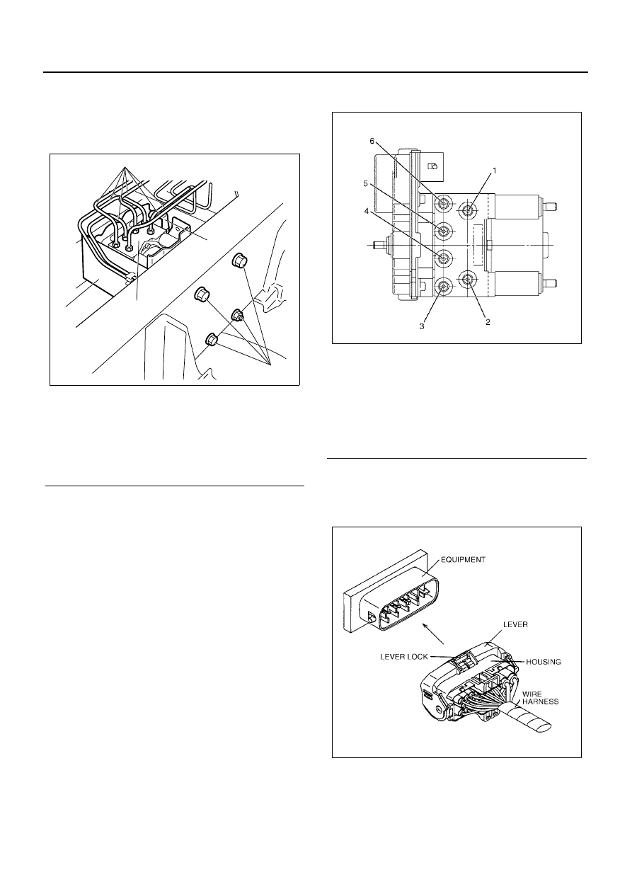
Legend
1. Master Cylinder (front)
2. Master Cylinder (rear)
3. Rear Right Wheel Cylinder
4. Rear Left Wheel Cylinder
5. Front Right Wheel Cylinder
6. Front Left Wheel Cylinder
N5A1041E
N5A1042E