Isuzu N-Series. Service manual - part 218


  Index      Isuzu     Isuzu N-Series - service and repair manual


Search            


Content   ..  216  217  218  219   ..


Isuzu N-Series. Service manual - part 218


HYDRAULIC BRAKES 5A-31

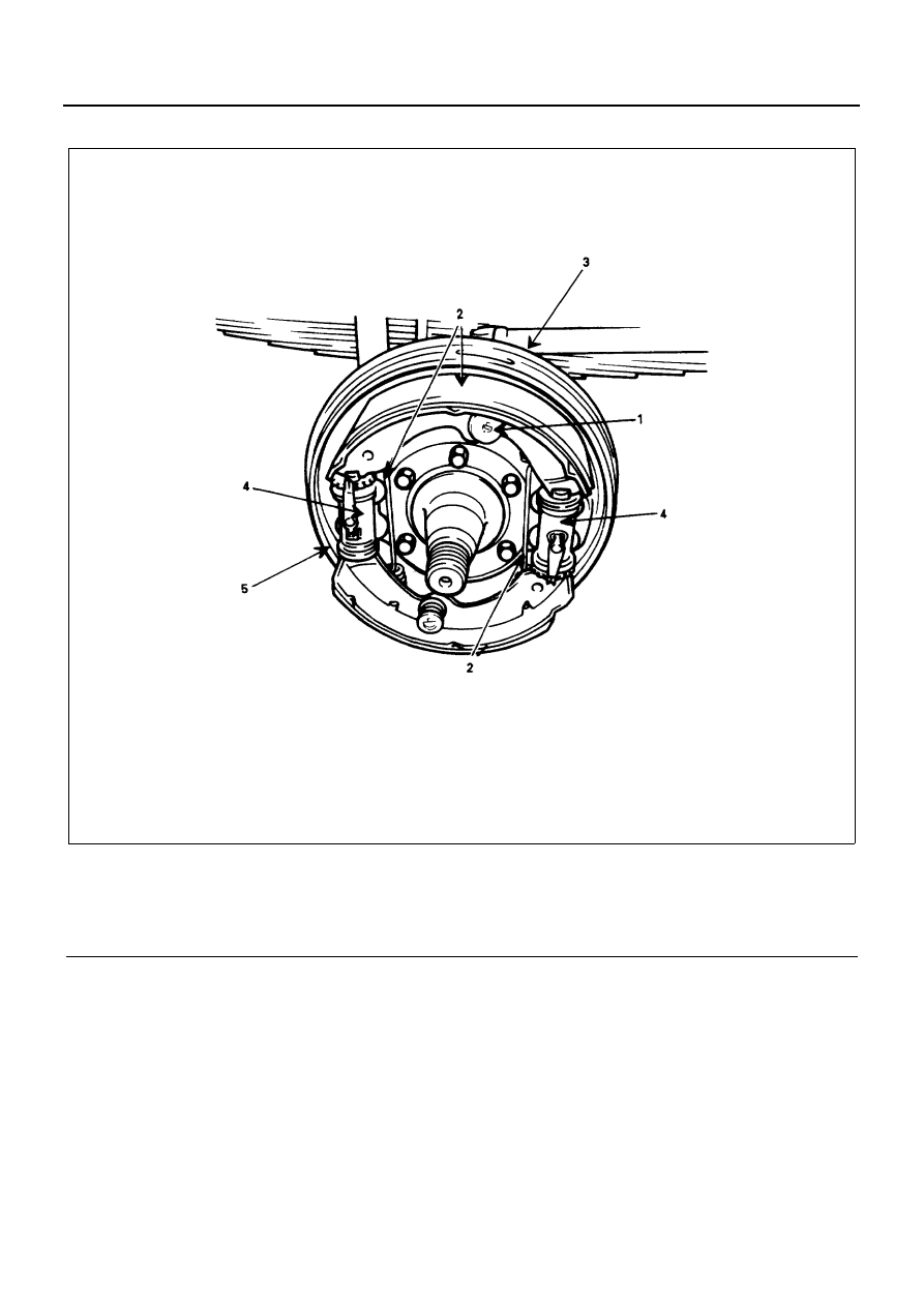
Dual Two Leading Type (D2L Type)

Legend

1. Shoe holding spring, cup and pin

4. Wheel cylinder assembly

2. Brake shoe and return spring

5. Back plate and oil shield cover

3. Brake flexible hose and pipe

N5A0127E

5A-32 HYDRAULIC BRAKES

Removal

If the brake drum has step wear or the brake drum edge
is corroded, it will be difficult to remove the brake drum.
The following procedure will make brake drum removal
easier.

1. Remove the rubber cover from the brake lining

clearance adjusting hole and auto-adjuster lever
release hole.

2. Remove the adjust hole cover and adjuster lever

release hole cover.

3. Using 

φ5 mm plus driver put it into the adjuster le-

ver release hole and then push up the adjuster le-
ver.

4. Put the slotted screwdriver into the adjuster hole

while push up the adjuster lever.

Legend

1. Corroded portion

Legend

1. Adjuster lever release hole cover
2. Adjust hole cover

N5A0128E

N5A0129E

Legend

1. Adjuster lever release hole

N5A0130E

N5A0131E

HYDRAULIC BRAKES 5A-33

5. Turn the adjuster gear to the marked arrow

“LOOSE” on the backing plate.

6. Shoe Holding Spring, Cup and Pin
7. Brake Shoe and Return Spring
8. Brake flexible Hose and Pipe

1) Place a tray beneath the flexible hose to re-

ceive the brake fluid.

2) Loosen the union nut (1).

3) Remove the clip (2) and loosen the hose end

(3) from the pipe to remove the flexible hose.

Notice:
Take care not to twist the piping and the flexible hose.

9. Wheel Cylinder Assembly

10. Back Plate and Oil Shield Cover 

Store all of the removed parts in a clean part tray.

Inspection and Repair

Make the necessary adjustments, repairs, and part re-
placements if excessive wear or damage is discovered
during inspection.
Brake Drum Inside Diameter
Visually inspect the brake drum for excessive wear and
scoring.
If the brake drum is scored or worn, lathed to the speci-
fied limit.
Use a vernier caliper to measure the brake drum inside
diameter.

Legend

1. Adjuster gear

N5A0132E

N5A0133E

N5A0136E

N5A0137E

5A-34 HYDRAULIC BRAKES

Brake Lining Thickness Measurement
Use a vernier caliper to measure the brake lining thick-
ness or the rivet depth.
If the measured value is less than the specified limit, the
brake shoe assembly and/or the lining must be re-
placed.

Brake Lining Removal (Riveted Type Only)

1. Remove the rivet caulking portions with a hammer

and chisel.

2. Remove the rivets with a hammer and punch.

3. Inspect the brake shoe for cracking.

Brake Lining Installation (Riveted Type Only)

1. Install the brake lining the rivets to the brake shoe.
2. Place the brake shoe assembly in the air hydraulic

riveter.

3. Use the air hydraulic riveter to set and caulk each

of the rivets.

4. Start riveting at the center of lining and work to-

wards the ends.

Brake Lining and Drum Contact

1. Apply chalk powder to the entire inside brake drum

surface.

Brake Drum Inside Diameter

mm (in)

Drum size

Standard

Limit

279.4
300.0
320.0 

279.4 (11.00)
300.0 (11.81)

320.0 (12.60)

281.0 (11.06)
301.5 (11.87)

321.5 (12.66)

Out of round:

• Limit: 0.13 mm (0.005 in)

Brake Lining Thickness or Rivet Depth

mm (in)

Limit

1.0 (0.039)

N5A0138E

N5A0139E

Legend

1. Adhesion type
2. Riveted type

N5A0140E

N5A0141E


Content   ..  216  217  218  219   ..