Isuzu N-Series. Service manual - part 215
HYDRAULIC BRAKES 5A-19
Notice:
Seal parts cannot be reused. When reassembling, be
sure to replace with a new seal kit.
1. Flexible hose
2. Pin bolt (Lock pin side)
3. Caliper assembly
• Slide the caliper assembly free from the inside.
4. Outer pad
5. Inner pad
6. Pad clips
7. Support assembly
• Remove the hub and disc before removing the
support assembly.
8. Wind guide
• Remove the hub and disc before removing the
wind guide.
9. Adapter
Disassembly
1. Place a piece of wood across the body assembly to
prevent piston damage.
2. Apply approximately 196 kPa (2.0 kg/cm
2
/ 28.4
psi) of compressed air to the body assembly oil
port to remove the pistons.
Inspection
1. All parts for wear distortion or other conditions and
replace as needed.
2. Inner and outer pads.
• Use a vernier caliper to measure the inner pad
and outer pad thickness.
• If the measured value is less than the specified
limit, the pads must be replaced with the repair
pad kit.
3. Piston and Cylinder Clearance.
• Use a micrometer to measure the piston diam-
eter.
• Use an inside dial indicator to measure the cyl-
inder bore.
Legend
1. Caliper Assembly
2. Support Assembly
3. Pin Bolt
3
1
2
N5A0432E
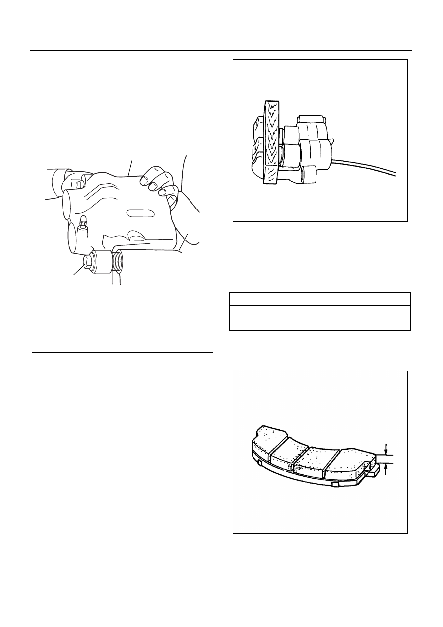
Pad Thickness
mm (in)
Standard
Limit
13 (0.51)
1 (0.04)
N5A0067E
N5A0093E