Isuzu N-Series. Service manual - part 210


  Index      Isuzu     Isuzu N-Series - service and repair manual


Search            


Content   ..  208  209  210  211   ..


Isuzu N-Series. Service manual - part 210


SERVICE INFORMATION 00-57
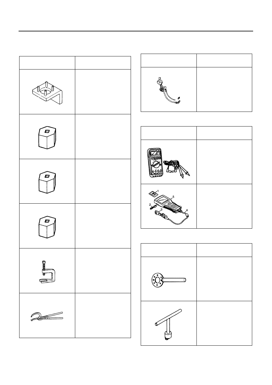
SPECIAL TOOLS

Hydraulic Brakes

Anti-lock Brake System (ABS)

Parking Brakes

Illustration

Tool Number / 

Description / Remarks

5-8840-2371-0 / Master 

cylinder support plate

5-8840-2370-0 / Wrench 

(Cylinder inside diame-

ter 30.1 mm

, 31.7 mm)

5-8840-2369-0 / Wrench 

(Cylinder inside diame-

ter 28.5 mm)

5-8840-2805-0 / Wrench

(Cylinder inside diame-

ter 34.9 mm)

5-8840-2215-0 / 

Remover: steering wheel

9-8522-0026-0 / 

Return spring plier

5884023710

5884023700

5884023690

5884028050

5884022150

9852200260

5-8840-2190-0 / Pres-

sure gauge: brake fluid

Illustration

Tool Number / 

Description / Remarks

5-8840-0285-0

(J-39200) / 

High impedance multim-

eter

1. PCMCIA Card
2. RS232 Loop Back 

Connector

3. SAE 16/19 Adapter
4. DLC Cable
5. Tech 2

Illustration

Tool Number / 

Description / Remarks

5-8840-2043-0 / Flange 

holder

1-8523-7002-0 / 

Return spring remover

Illustration

Tool Number / 

Description / Remarks

5884021900

5884002850

Tech 2

5884020430

1852370020

00-58 SERVICE INFORMATION

9-8522-1231-0 / 

Return spring setting tool

Illustration

Tool Number / 

Description / Remarks

9852212310

HYDRAULIC BRAKES 5A-1

BRAKES

SECTION 5A

HYDRAULIC BRAKES

Contents

GENERAL DESCRIPTION ................................... 5A-2

Hydraulic Brake System .................................... 5A-2
Hydraulic Booster Brake system ....................... 5A-3
Front Drum Brake .............................................. 5A-5
Front Drum Brake (Auto-adjuster Type) ............ 5A-6
Rear Drum Brake (Manual Adjuster Type) ........ 5A-7
Rear Drum Brake (Auto-Adjuster Type) ............ 5A-8
Auto-Adjuster................................................... 5A-10
Operation of Auto-adjuster .............................. 5A-15
Front Disc Brake.............................................. 5A-16
Load Sensing Proportioning Valve (LSPV)...... 5A-17
Deceleration Sensing Proportioning Valve (DSPV)..... 5A-17

ON-VEHICLE SERVICE ..................................... 5A-18

Front Disc Brake Assembly ............................. 5A-18
Front Disc Brake Pad ...................................... 5A-24
Front Drum Brake Assembly (Two Leading and Dual 
Two Leading)................................................... 5A-30
Rear Drum Brake Assembly (Except Drum Inside 
Diameter 370 mm)........................................... 5A-38
Rear Drum Brake Assembly (Drum Inside Diameter 
370 mm) .......................................................... 5A-46
Brake Pedal and Control ................................. 5A-50
Hydraulic Booster and Brake Pedal Assembly.... 5A-57
Hydraulic Booster ............................................ 5A-60
Accumulator and O-ring Replacement ............ 5A-62
Clevis and Lock Nut Replacement .................. 5A-63
Guard Replacement ........................................ 5A-64
Load Sensing Proportioning Valve .................. 5A-65
Deceleration Sensing Proportioning Valve ...... 5A-69

UNIT REPAIR ..................................................... 5A-71

Wheel Cylinder Assembly (without Auto-adjuster) ...... 5A-71
Wheel Cylinder Assembly (with Auto-adjuster)....... 5A-74
Master Cylinder Assembly (NHR).................... 5A-88
Master Cylinder Assembly (NKR / NPR / NQR / NPS) ..... 5A-91

5A-2 HYDRAULIC BRAKES

GENERAL DESCRIPTION

Hydraulic Brake System

The brake system has dual hydraulic circuit with vacuum
booster (Master-vac).
The master cylinders and the wheel cylinders at the front
and rear of the vehicle are connected by steel piping and
flexible hoses.
The vacuum booster is connected to the vacuum pump
through the vacuum tank. This provides the most effec-
tive vacuum assist.

N5A0044E


Content   ..  208  209  210  211   ..