Isuzu N-Series. Service manual - part 173
REAR AXLE 4B-49
Adjusting shims available,
0.10, 0.12, 0.14, 0.16, 0.18, 0.20 mm (0.004, 0.0047,
0.0055, 0.0063, 0.0071, 0.0079 in)
N4A0155E
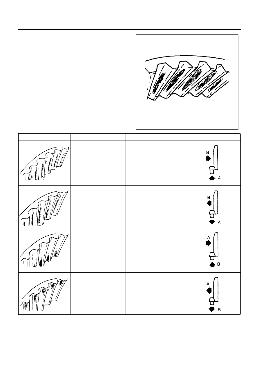
TOOTH CONTACT
CASE
ADJUSTMENT PROCEDURE
Drive pinion is too far
away from ring gear.
1. Move the drive pinion in to-
ward the ring gear by de-
creasing the thickness of
pinion depth adjusting
shims.
2. Adjust the backlash by
moving ring gear away
from the drive pinion.
Drive pinion is too close to
the ring gear.
1. Move the drive pinion away
from the ring gear by in-
creasing thickness of pin-
ion depth adjusting shims.
2. Adjust the backlash by
moving ring gear in toward
the drive pinion.
Ring gear is too close to
the drive pinion.
1. Move the drive pinion in to-
ward the ring gear by de-
creasing thickness of
pinion depth adjusting
shims.
2. Adjust the backlash by
moving ring gear away
from the drive pinion.
Ring gear is too for away
from drive pinion.
1. Move the drive pinion away
from the ring gear by in-
creasing thickness of pin-
ion depth adjusting shims.
2. Adjust the backlash by
moving ring gear in toward
the drive pinion.
N4A0156E
N4A0160E
N4A0157E
N4A0161E
N4A0158E
N4A0162E
N4A0159E
N4A0163E