Isuzu N-Series. Service manual - part 143
3C-20 FRONT SUSPENSION
Inspection and Repair
Make necessary correction or parts replacements if ex-
cessive wear, damage, corrosion or any other abnormal
condition are found through inspection.
Visual Check
Inspect the following parts for excessive wear, damage,
bending, oil leak or any other abnormal conditions.
• Torsion Bar
• End Piece
• Height Control Arm
• Rubber Bushings
• Strut Bar
• Shock Absorber
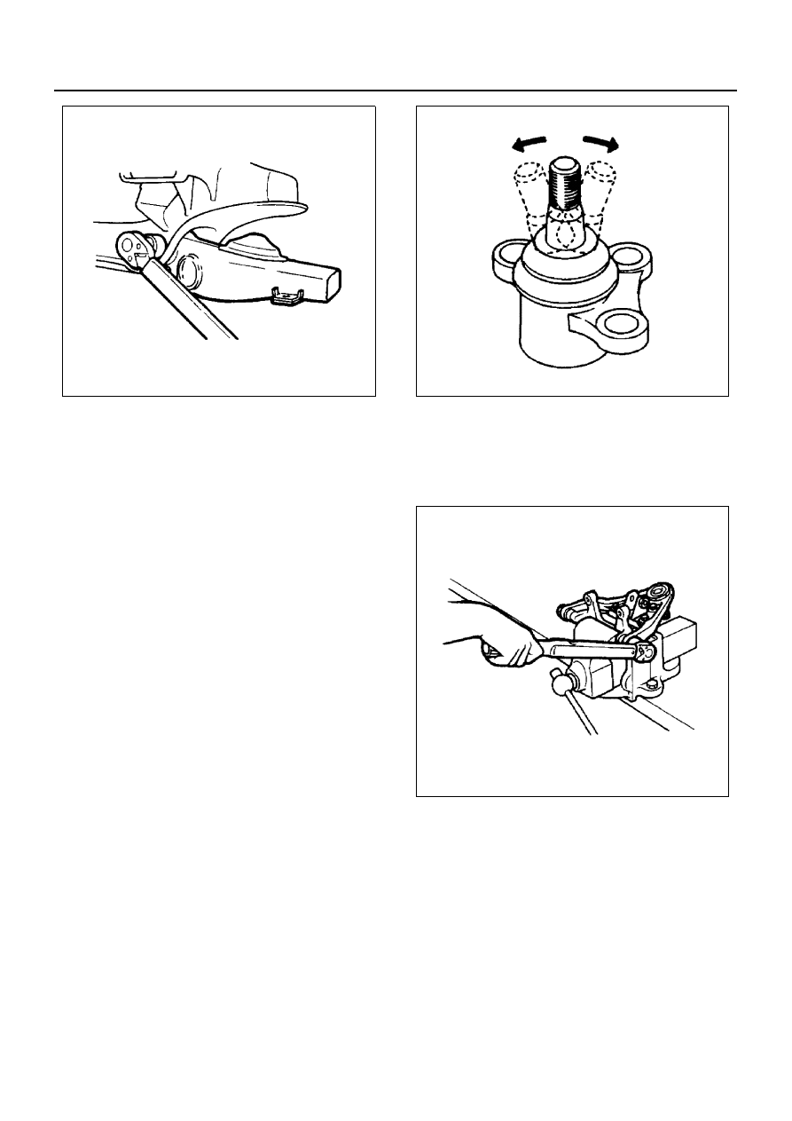
Ball Joint
• Inspect the ball joint boot for damage or grease
leak.
• Move the ball joint to confirm its normal movement.
• Inspect screw / taper area of ball for flaws.
If any defects are found by the above inspections, re-
place the ball joint with new one.
Upper Ball Joint Replacement
• Remove the ball joint fixing nut (Hex. 63mm).
• Remove the ball joint from the upper link using a
special tool.
Remover: 5-8840-2364-0
• Install the ball joint to the upper link using a bench
press and special tool.
Installer: 5-8840-2365-0
• Tighten nut to specified torque.
Tighten:
• Joint ball nut to 206 N
⋅m (21.0 kg⋅m/152 lb⋅ft)
N3A0389E
N3A0391E
N3A0392E