Content .. 1193 1194 1195 1196 ..
Isuzu N-Series. Service manual - part 1195
SRS CONTROL SYSTEM 9C-27
Data Display
Move the connector or harness by hand. If the display
changes from fix to release, connection of connector is
faulty, pin tip length is uneven, or open or short circuit in
the harness exists where you have moved. Therefore,
repair is necessary. When asterisk mark (*) is displayed
in place of numeric display; Problem of Tech 2.
If asterisk mark (*) is found any of the data, PCMCIA
card must be version upgraded.
Snapshot (Graph Plotting)
• The snapshot can record the data list menu and
plot a graph.
• Utilizing this mode, reproduce and record the con-
ditions claimed by the customer to identify the en-
gine data fault.
• The stored data can be replayed with a domestic
power supply.
Programming
• Before replacing SRS control unit, be sure to
check/save the vehicle information. After replace-
ment, input it.
List of Diagnostic Trouble Code
Caution:
• Trouble codes No. 21, 25, 71 cannot be cleared.
• Code No. 12 indicates that the system is normal.
F0 : Read the DTC in the order of priority.
F1 : Clear the DTC.
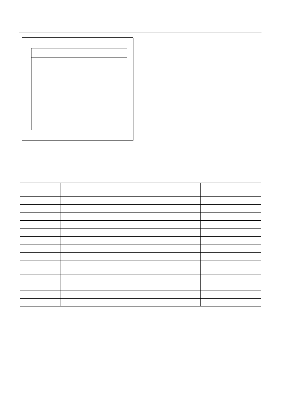
Application menu
N9A0075E
Trouble code
No.
Item to be detected
“SRS” warning lamp ON
14
Connector is half-connected
ON
21
Resistance of SRS airbag deployment circuit is large
ON
22
Resistance of SRS airbag deployment circuit is small
ON
24
SRS airbag deployment circuit is shorted to ground
ON
25
SRS airbag deployment circuit is shorted to ignition voltage
ON
26
SRS airbag deployment circuit is open
ON
51
SRS airbag deployment current had output
ON
53
Specific trouble when SRS airbag deployment current had output
ON
54
Deployment output by onboard deployment system communica-
tion
55
Vehicle type error
ON
61
Warning lamp circuit trouble
ON
63
Power supply voltage failure
ON
71
SRS control unit internal trouble
ON