Isuzu N-Series. Service manual - part 1179


  Index      Isuzu     Isuzu N-Series - service and repair manual


Search            


Content   ..  1177  1178  1179  1180   ..


Isuzu N-Series. Service manual - part 1179


SEAT BELT 9A-15

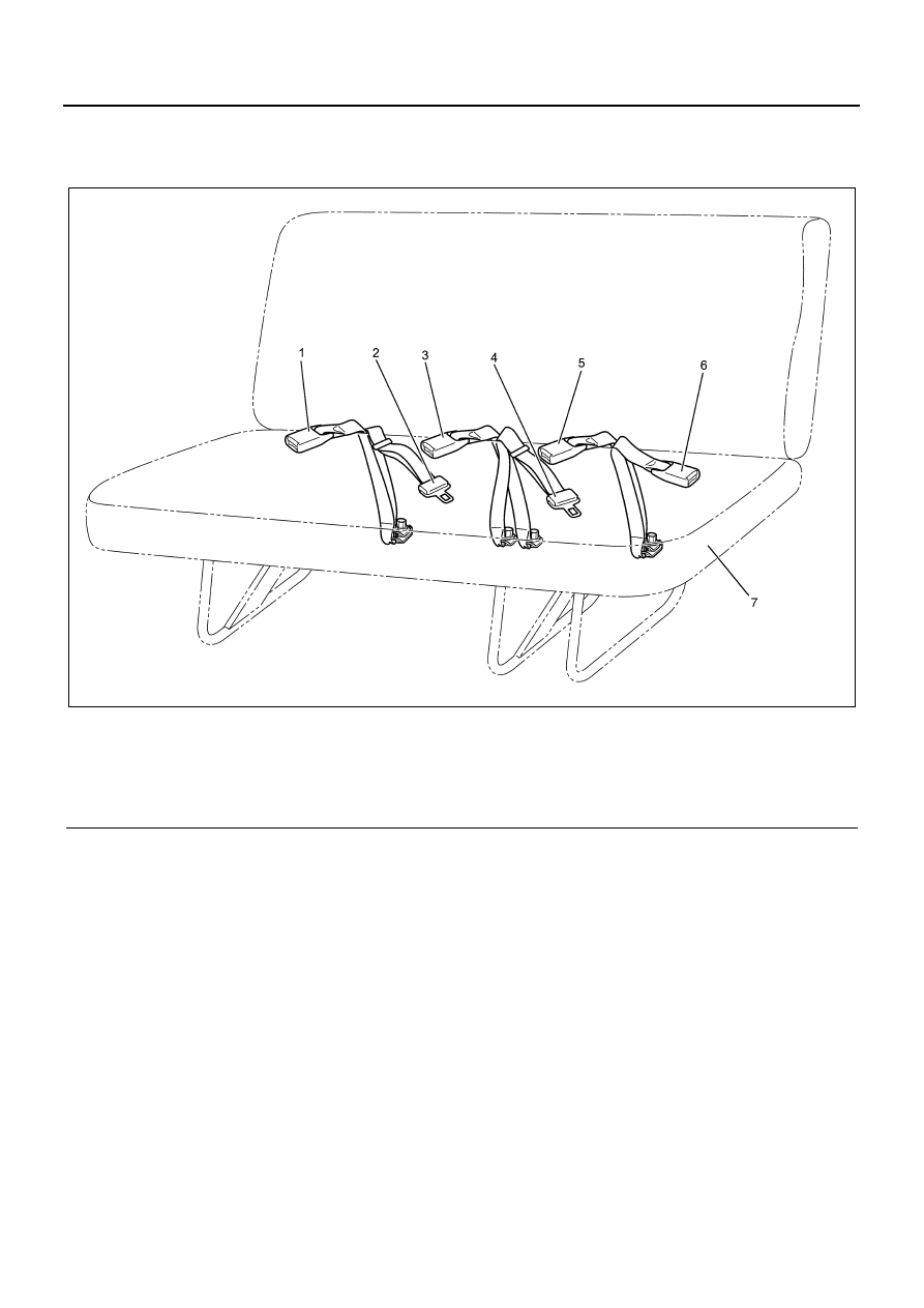
Rear Seat Belt Buckle and Rear Center Seat Belt/Buckle (Wide Cab Model)

Components

Legend

1. Rear seat belt buckle (RH)
2. Rear center seat belt (RH)
3. Rear center seat belt buckle (RH)
4. Rear center seat belt (LH)

5. Rear center seat belt buckle (LH)
6. Rear seat belt buckle (LH)
7. Rear seat cushion

Removal

Refer to “Rear Seat Belt Buckle and Rear Center Seat
Belt/Buckle (Narrow Cab Model)” in this section for re-
moval.

Installation

Refer to “Rear Seat Belt Buckle and Rear Center Seat
Belt/Buckle (Narrow Cab Model)” in this section for in-
stallation.

N2A0235E

9A-16 SEAT BELT

Fixing Torque

N2A0236E

SRS 9B-1

SEAT BELT, SRS AIRBAG

SECTION 9B

SRS

Contents

SRS System Assembly ......................................... 9B-2

Precautions on Service Work ............................ 9B-2

SRS Control Unit................................................... 9B-8

Precautions on Service Work ............................ 9B-8
Removal ............................................................ 9B-8
Installation ......................................................... 9B-8

SRS Airbag Assembly........................................... 9B-9

Precautions on Service Work ............................ 9B-9
Removal .......................................................... 9B-19
Installation ....................................................... 9B-20
Special Tool..................................................... 9B-22

Steering Wheel.................................................... 9B-23

Precautions on Service Work .......................... 9B-23
Removal .......................................................... 9B-23
Installation ....................................................... 9B-24
Special tool ...................................................... 9B-25

SRS Coil Assembly ............................................. 9B-27

Precautions on Service Work .......................... 9B-27
Removal .......................................................... 9B-27
Installation ....................................................... 9B-28
Special Tool..................................................... 9B-30

Steering Column ................................................. 9B-31

Precautions on Service Work .......................... 9B-31
Removal .......................................................... 9B-31
Installation ....................................................... 9B-33
Special tool ...................................................... 9B-36

9B-2 SRS

SRS System Assembly

Precautions on Service Work

WARNING:

WHEN SERVICING SRS SYSTEM PARTS (SRS CON-
TROL UNIT, AIRBAG, HARNESS, ETC.) OR ITS CIR-
CUMFERENCE, STOP TEMPORARILY THE
FUNCTION OF SRS ACCORDING TO THE PROCE-
DURE. FAILURE TO FOLLOW THE PROCEDURE
MAY CAUSE INJURY DUE TO SRS AIRBAG DE-
PLOYMENT OR UNNECESSARY REPAIR.

Turn the starter switch to “LOCK” at first. Then, discon-
nect the battery or remove the fuse which sends power
to SRS control unit. After that, do not perform the work
at least 15 seconds since airbag may be deployed. In
the service procedure, remove “SRS fuse” and detach
SRS airbag from deployment circuit to prevent unneces-
sary SRS parts from deploying.
If removing SRS airbag from deployment circuit accord-
ing to “Procedure to stop the function of SRS” in this top-
ic, service work can be performed immediately without
waiting for 15 seconds.

About Tools

WARNING:

WHEN SERVICING SRS, DO NOT USE ELECTRICAL
TEST EQUIPMENTS EXCEPT ONES DESCRIBED IN
THIS MANUAL TO AVOID DEPLOYMENT OF SRS
AIRBAG. FAILURE TO FOLLOW THIS MANUAL MAY
CAUSE INJURY DUE TO UNNECESSARY DEPLOY-
MENT OF SRS AIRBAG.

It is necessary to measure voltage and resistance. Fa-
miliarize yourself with use of Tech 2, SRS substitute
load (5-8840-2421-0), connector test adapter kit (5-
8840-0385-0), DVM (digital multi-meter, 5-8840-0366-
0).

Necessary Repair and Inspection After Collision

• If the parts of this system are damaged, replace-

ment is needed. If mounting portion of SRS parts
are damaged, replacement is needed.

• Never use system parts of other vehicle.
• Do not disassemble or repair SRS control unit,

SRS coil assembly or SRS airbag. These parts
must be replaced with new ones.

• Confirm the part number to make sure that replace-

ment SRS parts are legitimate.

Caution:

Do not use SRS airbag of other vehicle or model. Be
sure to confirm the part number to use appropriate SRS
airbag.

Caution:

After repair and replacement, set back the SRS airbag
to the correct specification so that it is operated properly.

It is necessary to replace SRS control unit and SRS air-
bag, and inspect the dimension of steering column. If the
mounting bracket of SRS control unit are damaged
clearly, replacement is needed. Besides, the dimension
of steering column should be inspected regardless of
SRS airbag deployment.

Replacement and Inspection of Parts After Collision
with Deployment
If frontal collision with airbag deployment occurs, follow-
ing system parts must be replaced. It is necessary to
check whether SRS coil assembly is damaged.

• SRS airbag assembly
• SRS control unit
• Combination switch assembly (including SRS coil)

Caution:

Refer to “Replacement guideline for SRS control unit”
described later for important information about replace-
ment of SRS control unit after collisions with deployment
and without.

• Inspect SRS coil assembly harness and connector

for burn due to excessive heat, dissolution or dam-
age. If damaged, refer to “SRS Coil Assembly”.

Inspection of Parts After Collision with or Without
Deployment
The certain parts of this system and supplemental re-
straint system should be inspected regardless of airbag
deployment. The parts to be inspected are shown as fol-
lows.

• Steering column: inspect the dimension according

to “Examination of damage for steering column”
described in “Steering column”.

• Steering support bracket: inspect for distortion,

bent, crack or other damage.

• Instrument panel bracket: inspect for distortion,

bent, crack or other damage.

• Seat belt and its mounting portion: refer to “Seat

Belt” section.

Replacement Guideline for SRS Control Unit
If collision with airbag deployment occurs, replacement
of SRS control unit is needed. If “SRS” warning lamp il-
luminates, perform SRS diagnosis according to “Func-
tion check: SRS system check” in “SRS control system”
in SRS Control System section.

Damaged Harness
If the SRS harness is damaged, it must be replaced.

Damaged SRS Connector (Case and Terminal)
If the connector or terminal of SRS harness (except lead
wire) is damaged, replace it.


Content   ..  1177  1178  1179  1180   ..