Content .. 1168 1169 1170 1171 ..
Isuzu N-Series. Service manual - part 1170
8-392 CAB AND CHASSIS ELECTRICAL
H-3
H-3
H-10
H-10
H-12
H-12
J-9
J-32
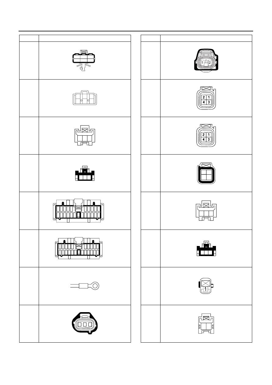
No.
Connector Face
006-014
1
2
3
4
5
6
006-015
1
2
3
4
5
6
003-010
3 2 1
003-009
1 2 3
022-001
1 2 3 4
13 14
5
6 7 8 9 10
15 16
17 18 19 20
11 12
21 22
022-002
9 8 7
20 19
6
5 4 3 2 1
18 17
16 15 14 13
22 21
12 11
10
000-001
003-018
1
2
3
J-50
J-128
J-155
J-155
L-2
L-2
N-2
N-6
No.
Connector Face
002-035
004-018
004-018
004-011
1
3
2
4
003-010
3 2 1
003-009
1 2 3
001-020
002-023
2 1