Isuzu N-Series. Service manual - part 1055


  Index      Isuzu     Isuzu N-Series - service and repair manual


Search            


Content   ..  1053  1054  1055  1056   ..


Isuzu N-Series. Service manual - part 1055


CAB AND CHASSIS ELECTRICAL 8-325

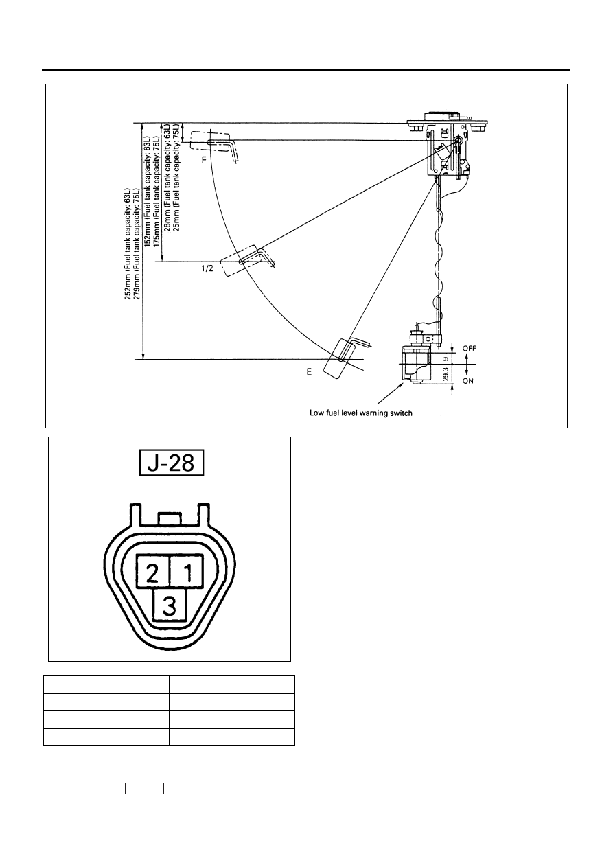
(Float type of warn low fuel level)

1. Check the resistance between the connector termi-

nals 1 

 and 3 

 while shifting the float

from “E” to “F” point.

2. Check if the low fuel warning light turns on when

the float is at “E” position. If found defective replace
the fuel tank unit.

N8A0352E

Float position

Resistance value (

Ω)

F

3

±2.1

1/2

32.5

±4.8

E

110

±7.7

N8A0331E

J-28

J-28

8-326 CAB AND CHASSIS ELECTRICAL

Removal
Preparation:
Disconnect the battery ground cable.

1. Fuel Tank Unit

1) Disconnect the connector.

2) Remove five screws.

Installation
To install, follow the removal steps in the reverse order.

Engine Speed Sensor

Inspection
Measure the resistance value between the engine
speed sensor connector terminals.
Replace the engine speed sensor when the result of
inspection is found abnormal.
4J Series engine = 1.36 — 1.86 K

4H Series engine = 0.57 — 0.86 K

N8A0353E

Float position

Resistance value (

Ω)

F

3

±2.1

1/2

32.5

±4.8

E

110

±7.7

N8A0331E

N8A0354E

CAB AND CHASSIS ELECTRICAL 8-327

Removal
Preparation:
Disconnect the battery ground cable.

1. Engine Speed Sensor

1) Disconnect the connector.
2) Remove the engine speed sensor.

Installation
To install, follow the removal steps in the reverse order.

Vacuum Switch

Inspection
When the pressure value is below 250

±30 mm Hg

(33.3

±4.0 kPa), check to see if there is continuity be-

tween the terminal and the ground. If no continuity, re-
place the switch with a normal one.

Removal
Preparation:
Disconnect the battery ground cable.

1. Vacuum Switch

1) Disconnect the connector.
2) Remove the vacuum switch.

Installation
Apply liquid gasket to the screw portion of the switch to
prevent vacuum leak.

Vacuum Warning Buzzer

Inspection
Apply battery voltage to the buzzer connector terminals
to check the buzzer sound.
Replace the buzzer when the result of inspection is
found abnormal.
Removal
Preparation:
Disconnect the battery ground cable.

1. Meter Assembly

Refer to “METER ASSEMBLY” in this section.

2. Vacuum Warning Buzzer

1) Disconnect the connector.
2) Remove the buzzer fixing screw.

N8A0355E

N8A0356E

N8A0357E

8-328 CAB AND CHASSIS ELECTRICAL

Installation
To install, follow the removal steps in the reverse order.

Water Sedimenter Switch

Inspection

1. When the float in the water sedimenter is above the

drain warning level, confirm if there is continuity be-
tween the switch connector terminals.

2. Turn the starter switch on, disconnect the water

sedimenter connector and connect the harness
side connector terminals. Then confirm that the
sedimenter warning light turns on.
If found defective, replace the switch or repair a
poor connection or an open circuit between the
connector terminals.

Brake Fluid Switch

Inspection

1. Confirm there is continuity between the switch con-

nector terminals when the brake fluid in the tank is
between 60 — 75 cc level.

2. Turn the switch on, disconnect the brake fluid

switch connector and connect the harness side
connector terminals. Then confirm that brake
warning light turns on.
If found defective, replace the tank, or repair a poor
connection or an open circuit between the connec-
tor terminals.

Removal
Preparation:
Disconnect the battery ground cable.

1. Instrument Panel Assembly

Refer to “INSTRUMENT PANEL” of section 2.

2. Brake Fluid Tank (Brake Fluid Switch)

1) Disconnect the switch connector.
2) Remove four fixing nuts.
3) Drain brake fluid in the tank.
4) Disconnect the tubes.

Caution:
Be very careful not to allow the brake fluid to come in
contact with painted surfaces or resin parts surfaces.

Legend

1. Meter Assembly
2. Vacuum Warning Buzzer

1

2

N8A0358E

N8A0359E

N8A0360E


Content   ..  1053  1054  1055  1056   ..