Isuzu N-Series. Service manual - part 1042


  Index      Isuzu     Isuzu N-Series - service and repair manual


Search            


Content   ..  1040  1041  1042  1043   ..


Isuzu N-Series. Service manual - part 1042


CAB AND CHASSIS ELECTRICAL 8-273

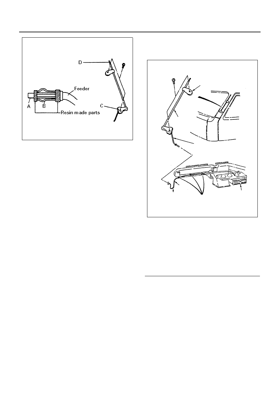
In checking, measure the following three points with the
circuit tester in the range of “resistance x 1 (

Ω).”

Between A and B
No continuity (No reading at the indicator) 

Normal
Continuity (A bite in the feeder. The core grounded) 

Lower reception
Between B and C
Continuity (Indicator reading: 0

Ω) → Normal

No continuity (Shielded core disconnected or defective
grounding at the screw 

→ Hampered by noise)

Between A and D
Continuity or no continuity
There are some antenna feeders and relay feeders with
a condenser built in their connections.
Measuring resistance between the two points does not
result in correct judgment. Connect temporarily another
normal antenna to the radio and check to see if its re-
ception is audible. Most antenna now available are slide
type. Rust at the screw C and the cab panel where
grounded would lead no continuity, followed by lower re-
ception.
Keep this portion clean to avoid rust.
Removal
Preparation:
Disconnect the battery ground cable.

1. Antenna

1) Disconnect the joint connector.
2) Remove the upper and lower side antenna

bracket.

3) Pull out the antenna feeder.

Notice:
For easier fitting, tie the lead wire to the end of the an-
tenna feeder in advance.

Installation
To install, follow the removal steps in the reverse order.

Speaker

Inspection

1. With the circuit tester set to the range of 

× 1 (Ω),

connect the circuit tester probes (red and black) to
the (+) and (

−) terminals of the speaker.

2. When the speaker is normal, a low buzzing sound

is heard.

3. When the speaker is defective, no sound is heard.

However, the distortion or chattering of the sound
cannot be identified.
When the speaker is installed to the vehicle, dis-
connect the connectors before checking. 

N8A0289E

Legend

1. Antenna
2. Antenna Bracket
3. Feeder
4. Joint Connection
5. Feeder
6. Clip
7. Radio

1

2

3

4

5

6

7

N8A0394E

8-274 CAB AND CHASSIS ELECTRICAL

When no sound is heard, the following are consid-
ered as the cause.

• The speaker wiring is disconnected at the speaker

terminals.

• The speaker body is defective.
• There is an open circuit somewhere in the speaker

harness on the vehicle side.

• The speaker harness on the vehicle side is ground-

ed or caught up.

Removal
Preparation:
Disconnect the battery ground cable.

1. Door Pad

Refer to “FRONT DOOR TRIM PAD” of section 2.

2. Speaker Panel

Disconnect the speaker connector.

3. Speaker
4. Waterproof Sheet

Installation
To install, follow the removal steps in the reverse order.

Cigar Lighter

Removal
Preparation:
Disconnect the battery ground cable.

1. Center Cluster

Refer to “RADIO” in this section.

2. Cigar Lighter Assembly

Remove the nut, then remove cigar lighter assem-
bly, bezel and outer case.

Installation
To install, follow the removal steps in the reverse order.

Meter and Warning/indicator Light

General Description

The circuit consists of the starter switch, meter assem-
bly, vacuum tank switch, seat belt switch, oil pressure
switch, fuel sedimenter switch, brake fluid switch, park-
ing brake switch, vehicle speed sensor, fuel tank unit,
thermo unit and engine speed sensor.
The meter assembly contains the speedometer, ta-
chometer, fuel meter, thermometer and the warning/in-
dicator light.
The meter warning/indicator lights and their bulb sock-
ets are a unit, they are installed from the back of the
speedometer assembly.

Legend

1. Trim Panel
2. Speaker Panel
3. Speaker
4. Waterproof Sheet

N8A5341E

Legend

1. Bezel
2. Cigar Lighter Assembly
3. Center Cluster
4. Outer Case
5. Nut

2

1

4

5

3

N8A0395E

CAB AND CHASSIS ELECTRICAL 8-275

Parts Location

For 12 Volt

A

FRAME

HARNESS

E-14

OIL PRESSURE

SWITCH

E-7

THERMO UNIT

H-14

H-14

E-2

TACHO

SENSOR  

H-14

E-7

THERMO UNIT 

<4JB1>

<4JH1>

<4JH1>

FUSE BOX ASM

F-4,F-7,F-16

B-55 METER

B-334, B-335

TACHOGRAPH

(IN METER)

B-338

TACHOGRAPH

(IN INST)

H-5~H-7

B-1

B-67

B-337

PLUS CONVERTER

B-7

H-12

J-9

B-71 VACUUM

TANK SW

B-85 BRAKE

OIL LEVEL SW

STARTER

J-8 OIL

PRESSURE SW

(Except 4JH1)

J-128

HBB LEVEL SW

FL-1,FL-2 FUSIBLE LINK

RELAY BOX

ASM

P-1

P-2

P-5

BATTERY

J-32 VEHICLE

SPEED SENSOR

J-28 

FUEL TANK UNIT

N-6 

PARKING BRAKE SW

J-53,J-54 

FUEL SEDIMENTER

STATER SW

B-52 METER

B-51 METER

B-336 METER

(4JH1)

A

N-5

P-5

P-1

(12V)

P-2

P-4

P-3

<4JH1>

B-236 

AIR PRESSURE

SWITCH

X-5 ABS

INDICATOR RELAY

B-18 DIODE

X-33 DIODE  

X-13 BUZZER

CANCEL RELAY

N8A0534E

8-276 CAB AND CHASSIS ELECTRICAL

For 24 Volt

<4HE1, 4HF1, 4HG1, 4HK1>

J-28

FUEL TANK UNIT

N-6

PARKING BRAKE SW

J-32 VEHICLE SPEED SENSOR

E-2

TACHO SENSOR

H-14

P-5

P-1

P-2

P-3

P-4

RELAY BOX ASM

FL-1, FL-2

FUSIBLE LINK

J-9

H-12

B-67

B-7

B-1

H-5, H -7, H-8

STARTER

J-8 

OIL PRESSURE SW

B-71 

VACUUM TANK SW

B-85 

BRAKE FLUID LEVEL SW

BATTERY

H-14

STARTER SW

B-52 

METER

B-51 

METER

B-55 

METER

FUSE BOX ASM

F-4, F-7, F-16

E-76 THERMO 

SENSOR(UNIT)

J-128

HBB LEVEL SW

X-13 BUZZER

CANCEL RELAY 

B-18

DIODE

B-236 

AIR PRESSURE

SWITCH

X-33 

DIODE

X-5 ABS 

INDICATOR RELAY

J-53, J-54

FUEL SEDIMENTER

N-5

SEAT BELT SW

N8A0535E


Content   ..  1040  1041  1042  1043   ..