Isuzu N-Series. Service manual - part 1039


  Index      Isuzu     Isuzu N-Series - service and repair manual


Search            


Content   ..  1037  1038  1039  1040   ..


Isuzu N-Series. Service manual - part 1039


CAB AND CHASSIS ELECTRICAL 8-261
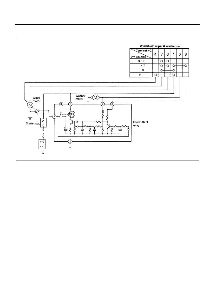
Intermittent Relay

Circuit Diagram

Removal
Preparation:
Disconnect the battery ground cable.

1. Glove Box

Open the lid and remove the four screws.

2. Intermittent Relay

1) Press A position with your finger and pry up B

position with the tip of a screw-driver.

2) When the relay moves up by about 2/3 of its

size, tilt and take off the relay to avoid interfer-
ence with the instrument panel.

3) Disconnect the connector.

N8A0267E

8-262 CAB AND CHASSIS ELECTRICAL

Installation
To install, follow the removal steps in the reverse order.

Windshield Wiper Arm & Blade

Removal

1. Cover
2. Wiper Arm Nut
3. Wiper Arm & Blade

Installation
To install, follow the removal steps in the reverse order,
noting the following points.

1. Before installing the wiper arm & blade to the shaft,

confirm that the motor stops at the auto-stop posi-
tion.

2. Set the wiper arm & blade so that the tips of both

blades are positioned as shown in the illustration.

3. Tighten the wiper arm nut to the specified torque.

Tighten:
Wiper arm nut to 17 N

⋅m (170 kg⋅cm/147 lb⋅in)

Instrumental panel

Instrument
panel rein-
forcement

1

2

2

A

S

B

View  S

N8A0268E

3

2

1

N8A0269E

Approx. 45mm(STD Cab)
Approx. 70mm(Wide Cab)

N8A0270E

CAB AND CHASSIS ELECTRICAL 8-263

Windshield Wiper Linkage

Location of Rod and Pivot

Removal
Preparation:
Disconnect the battery ground cable.

1. Wiper Arm & Blade

Remove the cover, nut and wiper arm & blade.

2. Pivot Nut

Remove the rubber seal, nut and retaining rubber.

Pivot (Wiper: LH)

Rod

Rod

Pivot (Wiper: RH)

Wiper motor

N8A0271E

1

Nut

Cover

N8A0272E

Rubber seal

2

Retaining rubber

N8A0273E

8-264 CAB AND CHASSIS ELECTRICAL

3. Instrument Panel Assembly

Refer to “INSTRUMENT PANEL” of section 2. 

4. Wiper Motor

1) Remove the four screws.
2) Disconnect the ball joint between the crank arm

and the wiper link.

5. Instrument Panel Reinforcement

Refer to “INSTRUMENT PANEL” of section 2.

6. Wiper Link Assembly

Remove two retaining nuts from left hand side of
pivot.

3

N8A0274E

N8A0275E

N8A0276E

6

Pivot (Wiper: LH)

N8A0277E


Content   ..  1037  1038  1039  1040   ..