Isuzu N-Series. Service manual - part 1035


  Index      Isuzu     Isuzu N-Series - service and repair manual


Search            


Content   ..  1033  1034  1035  1036   ..


Isuzu N-Series. Service manual - part 1035


CAB AND CHASSIS ELECTRICAL 8-245

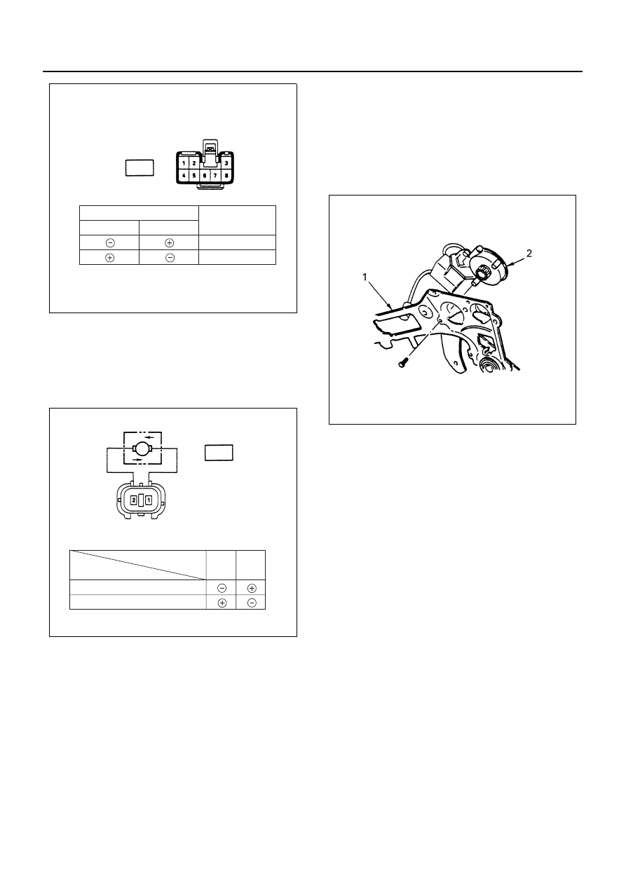
2. Inspection of the driver seat side motor

Remove the motor connector and apply battery
voltage to the motor side connector terminals to
check its function.
Replace the motor when the result of inspection is
found abnormal.

Removal
Preparation:
Disconnect the battery ground cable.

1. Window Regulator Assembly

Refer to Section 2 for Window Regulator and
Glass.

2. Power Window Motor

Remove three screws.

Installation
To install, follow the removal steps in the reverse order.

Connecting terminal

1 (L/W)

2 (L)

Operation

DOWN

UP

Harness side

D-3

N8A0240E

D-2

M

1

2

DOWN

UP

Terminal No.

Direction 
of operation

N8A0241E

N8A0242E

8-246 CAB AND CHASSIS ELECTRICAL

Front Passenger Seat Side Power Window Mo-
tor

Inspection
Before checking to see if the motor functions correctly,
be sure to check the circuit through the front passen-
ger’s switch connector 

 and the driver’s power win-

dow switch connector 

.

If the motor does not operate smoothly, either the motor
or the circuit between the switch and the motor is defec-
tive.

1. Circuit inspection of the front passenger seat side

window
Disconnect the switch connector and apply battery
voltage to the harness side connector terminals to
check its function.

2. Circuit inspection of the driver seat side switch

Disconnect the switch connector and apply battery
voltage to the harness side connector terminals to
check its function.

3. Inspection of the front passenger window motor

Disconnect the motor connector and apply battery
voltage to the motor side connector terminals to
check its function.
Repair or replace the motor when the result of in-
spection is found abnormal.

Removal
Preparation:
Disconnect the battery ground cable.

1. Window Regulator Assembly

Refer to Section 2 for Window Regulator and
Glass.

2. Power Window Motor

Remove three screws.

Installation
To install, follow the removal steps in the reverse order.

D-7

D-3

D-7

Harness side

Connecting terminal

Direction of

3 (L/Y)

5 (BR/Y)

operation

DOWN

UP

N8A0243E

Harness side

D-3

Connecting terminal

Direction of

4 (G/Y)

5 (R/Y)

operation

DOWN

UP

+

+

N8A0244E

D-6

M

1

2

DOWN

UP

Terminal No.

Direction 
of operation

N8A0245E

N8A0246E

CAB AND CHASSIS ELECTRICAL 8-247

Windshield Wiper and Washer

General Description

The circuit consists of the starter switch, windshield wiper & washer switch, wiper motor, washer motor and the inter-
mittent relay.
When the wiper & washer switch is turned on with starter switch on, the battery voltage is applied to the wiper motor
to activate the wiper.
The washer motor squirts glass cleaning fluid while the washer switch is being pushed. The intermittent relay is used
to control motion of the wiper.

Operation of Windshield Wiper Motor

(When wiper “LO” or “INT” position)

Notice:
Arrow marks indicate the direction of current.

N8A0250E

8-248 CAB AND CHASSIS ELECTRICAL

Parts Location

B-7

X-1 KEY ON RELAY

(12V ONLY)

X-11 KEY ON RELAY (24V ONLY)

RELAY BOX ASM (No.1)

N8A0251E


Content   ..  1033  1034  1035  1036   ..