Isuzu N-Series. Service manual - part 85


  Index      Isuzu     Isuzu N-Series - service and repair manual


Search            


Content   ..  83  84  85  86   ..


Isuzu N-Series. Service manual - part 85


2-46 CAB AND FRAME

Installation

For installation, reverse the removal procedure taking
the following point into consideration.

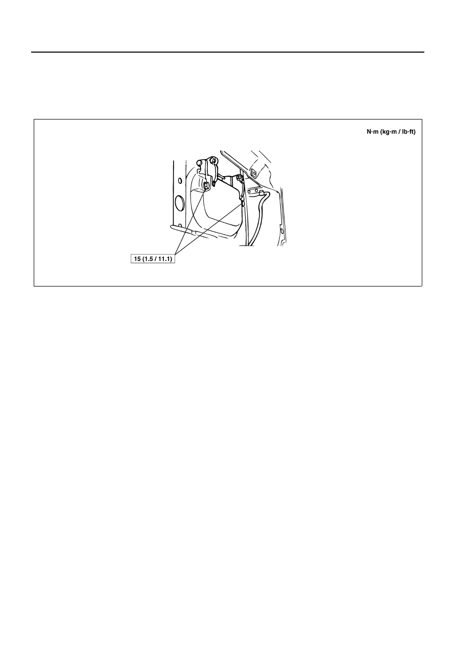
1. Tighten the door outside handle mounting bolts to

the specified tightening torque.

Tighten:
15 N

⋅m (1.5 kg⋅m/11.1 lb⋅ft)

Fixing Torque

N2A0082E

CAB AND FRAME 2-47

Rear Door Lock Mechanism

Removal

1. Remove the Rear door trim panel.

• Refer to “Rear door trim panel” in this section.

2. Peel off the water-proof sheet carefully with a cut-

ter or knife. Take care not to damage it when peel-
ing it off and remove the water-proof sheet.

3. Remove the 2 mounting screws and pull the rear

channel out and remove the glass run rear chan-
nel.

4. Remove the 3 mounting screws and disconnect the

locking links and remove the lock mechanism.

Legend

1. Rear door trim panel

3. Glass run rear channel

2. Water-proof sheet

4. Lock mechanism

N2A0083E

N2A0084E

2-48 CAB AND FRAME

Installation

To install, follow the removal steps in the reverse order,
noting the following points:

1. Tighten the mounting screw to the specified torque.

Tighten:

• Rear door lock mechanism mounting screws to 6 N

⋅m

(61.1 kg

⋅cm/52 lb⋅in)

2. After installation, check the operation.

Rear Door Outside Door Release Handle

Removal

1. Remove the rear door trim panel.

• Refer to “Rear door trim panel” in this section.

2. Remove the water-proof sheet.

• Refer to “Rear door lock mechanism” in this

section.

3. Disconnect the link and remove the 2 mounting

bolts and remove the Outside door release handle.

Legend

1. Rear door trim panel

3. Outside door release handle

2. Water-proof sheet

N2A0085E

CAB AND FRAME 2-49

Installation

To install, follow the removal steps in the reverse order,
noting the following point:

1. Tighten the mounting bolt to the specified torque.

Tighten:

• Outside door release handle mounting bolts to 13

N

⋅m (132.6 kg⋅cm/113 lb⋅in) — 18 N⋅m (1.8 kg⋅m/13

lb

⋅ft)

Keyless Entry Control Unit

Removal

1. Meter cluster

• Refer to “Meter Assembly” in Meter Section.

2. Tail/stop lamp malfunction warning relay

• Release the claw to remove it together with

bracket.

• Disconnect the connector (1).
• Remove the distributor (3) from bracket.
• Remove the mounting screw and remove the

control unit (2) together with bracket (4).

3. Register the ID code.

• Refer to “Keyless Entry” in Wiring Diagram

Section.

4. Check whether the keyless entry system operates

properly.

Installation

For installation, reverse the removal procedure taking
the following points into consideration.

Legend

1. Outside door release handle

N2A0086E

N2A0087E

N2A0088E


Content   ..  83  84  85  86   ..