Isuzu N-Series. Service manual - part 78


  Index      Isuzu     Isuzu N-Series - service and repair manual


Search            


Content   ..  76  77  78  79   ..


Isuzu N-Series. Service manual - part 78


2-18 CAB AND FRAME

Installation

For installation, reverse the removal procedure taking
the following points into consideration.

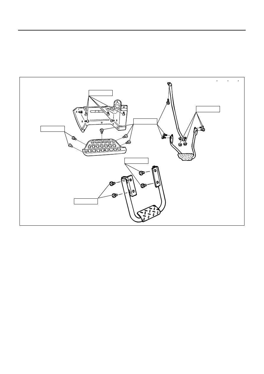
1. Tighten the mounting bolts and nuts to the speci-

fied tightening torque.

Tighten:
Mounting bolts and nuts to 15 N

⋅m (1.5 kg⋅m/11.1 lb⋅ft)

2. Make sure that the clip gets caught the tip of check

arm pin securely.

Fixing Torque

15 (1.5/11.1)

15 (1.5/11.1)

15 (1.5/11.1)

15 (1.5/11.1)

15 (1.5/11.1)

15 (1.5/11.1)

N  m (kg  m / lb  ft)

N2A0225E

CAB AND FRAME 2-19

Rear Step (Crew Cab Model)

Component

Removal

1. Fixing bolts

• Remove the 4 fixing bolts.

2. Rear step

Installation

For installation, reverse the removal procedure taking
the following points into consideration.

1. Tighten the fixing bolts to the specified torque.

Tighten:
Fixing bolt to 15 N

⋅m (1.5 kg⋅m/11.1 lb⋅ft)

Legend

1. Fixing bolt

2. Rear step

N2A0036E

2-20 CAB AND FRAME

Fixing Torque

N2A0037E

CAB AND FRAME 2-21

INSTRUMENT PANEL

Instrument Panel Assembly

Legend

1. Meter cluster

9. Instrument panel assembly

2. Center cluster

10. Vent duct

3. Glove box

11. Instrument panel extension

4. Under cover

12. Ashtray (driver’s seat side)

5. Meter assembly

13. Side defroster nozzle

6. Front cover

14. Fluid tank cover

7. Instrument side grommet

15. Relay lid

8. Idling control cable

N2A0038E


Content   ..  76  77  78  79   ..