Isuzu N-Series. Service manual - part 56


  Index      Isuzu     Isuzu N-Series - service and repair manual


Search            


Content   ..  54  55  56  57   ..


Isuzu N-Series. Service manual - part 56


1A-18 HEATING AND VENTILATION

Removal

Preparation:
Disconnect the battery ground cable.
[Driver Side]

1. Meter CIuster

Refer to Section 2 “CAB AND FRAME” for Meter
Cluster removal procedure.

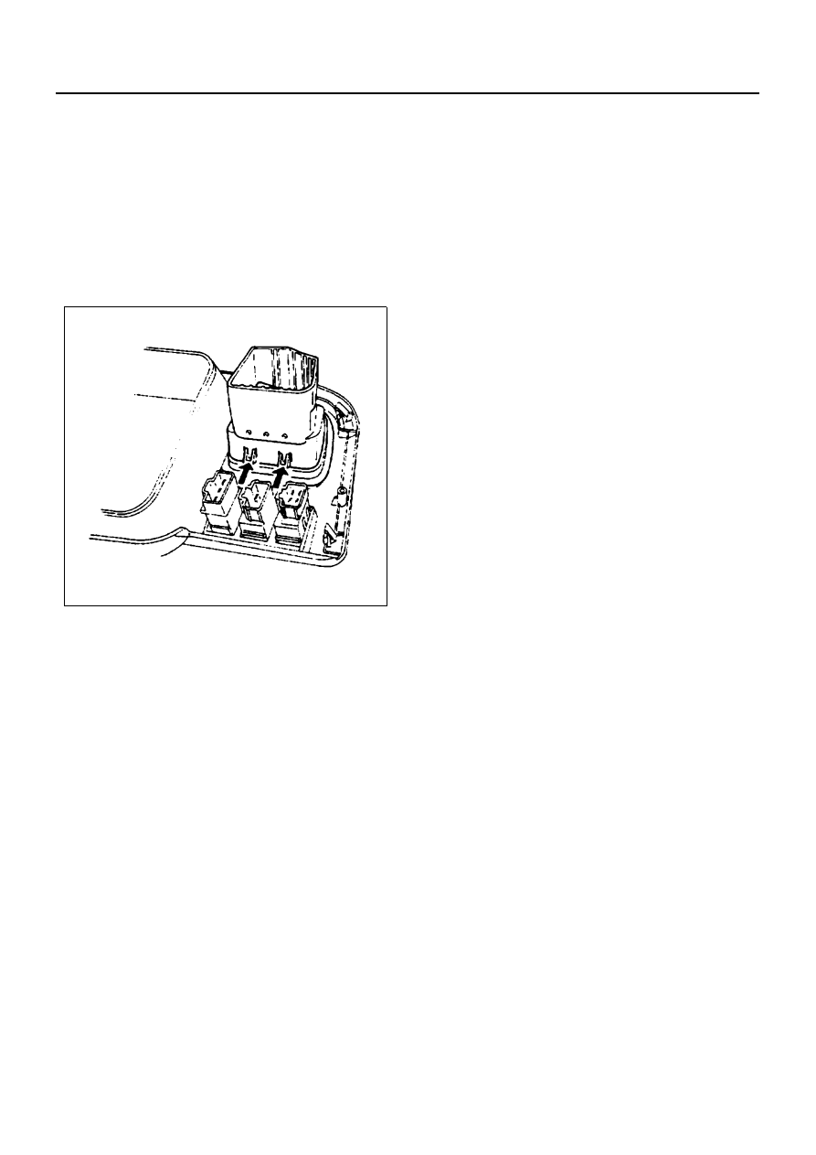
2. Ventilation Grille

Push the catches of the grille on the backside of
the cluster to the inside, and remove the ventilation
grille.

[Passenger Side]

1. Instrument Panel Assembly

Refer to Section 2 “CAB AND FRAME” for Instru-
ment Panel removal procedure.

2. Ventilation Duct
3. Ventilation Grille

Installation

To install, follow the removal steps in the reverse order.

N1A0035E

HEATING AND VENTILATION 1A-19

Defroster Nozzle/Ventilation Duct

Removal

Preparation:
Disconnect the battery ground cable.

1. Instrument Panel Assembly

Refer to Section 2 “CAB AND FRAME” for Instru-
ment Panel removal procedure.

2. Ventilation Duct (RH)
3. Ventilation Duct (CTR)
4. Ventilation Duct (LH)
5. Reinforcement Stay
6. Defroster Nozzle
7. Side Defroster Nozzle

Installation

To install, follow the removal steps in the reverse order.

Legend

1. Instrument panel assembly

6. Defroster nozzle (It is not installed on the vehicle with 

forged air ventilation as an optional equipment.)

2. Ventilation duct (RH)
3. Ventilation duct (CTR)

7. Side defroster nozzle (It is not installed on the vehicle 

with forged air ventilation as an optional equipment.)

4. Ventilation duct (LH)
5. Reinforcement stay

N1A0036E

1A-20 HEATING AND VENTILATION

Control Lever Assembly

Legend

1. Glove box

7. Control lever assembly

2. Center cluster

8. Fan switch connector

3. Knob

9. A/C switch connector

4. Control panel bezel

10. Illumination bulb connector

5. Control cable

11. Clip

6. A/C switch (A/C only)

N1A0037E

HEATING AND VENTILATION 1A-21

Removal

Preparation:
Disconnect the battery ground cable.

1. Glove Box

Open the glove box and remove the fixing screws.

2. Center Cluster

• While pulling the cluster with care, remove the

upper and the back side clips (1) of the cluster.

• Disconnect the cigar lighter and illumination

connectors.

3. Knob
4. Control Panel Bezel

Push the four catches at both sides of the bezel to
the inside, and remove the illumination bulb (1)
from the bezel (2).

5. Control Cable

Disconnect the control cables from the heater and
blower units.

6. A/C Switch

Push the catches at both sides of the A/C switch to
the inside, and remove the A/C switch by pulling it
out.

7. Control Lever Assembly

• Remove the lever fixing bolts and pull the lever

assembly out.

• Disconnect the A/C switch connector clip and

fan switch connector from the lever assembly.

• Remove the control cable fixing clip.

Installation

To install, follow the removal steps in the reverse order,
noting the following points:

1. Adjust the control cables.

Air source control cable
1) Slide the control lever to the left (“CIRC” posi-

tion).

2) Connect the control cable at the “CIRC” posi-

tion of the link unit of blower assembly and fix it
with the clip.

Temperature control cable
1) Slide the control lever to the left/right (“MAX

COLD”/“MAX HOT” position).

N1A0038E

N1A0039E

Legend

1. A/C switch
2. Control lever
3. Catch

N1A0040E


Content   ..  54  55  56  57   ..