Isuzu N-Series. Service manual - part 17


  Index      Isuzu     Isuzu N-Series - service and repair manual


Search            


Content   ..  15  16  17  18   ..


Isuzu N-Series. Service manual - part 17


POWER TAKE OFF 00-63

4. Battery Terminal

• Install the battery terminal securely and tighten

it.

5. PTO Output Propeller Shaft

• Turn the PTO to ON and tighten the tightening

nut of PTO output flange to the specified
torque.

Tighten:

PTO output flange nut to 105 N

⋅m (10.7 kg⋅m / 77 lb⋅ft)

• Install the propeller shaft, which is connected to

equipment, to the flange portion of PTO.

Tighten:

Propeller shaft to 17 N

⋅m (1.7 kg⋅m / 13 lb⋅ft)

Unit Repair

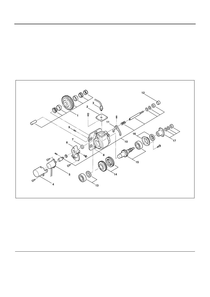
Electronic Control Type PTO Body

Legend

1. Idle shaft, idle gear, taper roller bearing

10. Solenoid plunger, washer, shift rod, spring (plain 

washer, nut)

2. Upper cover
3. PTO switch

11. Shift fork

4. Solenoid cover

12. Plug

5. Solenoid assembly

13. Front bearing, thrust collar

6. Adapter

14. Gear, sleeve

7. Oil seal

15. Output shaft, rear bearing

8. Gear case

16. Rear cover, oil seal

9. Spring pin

17. Nut, washer, flange

NPA0144E

00-64 POWER TAKE OFF

Disassembly

Disassembly Steps

1. Cover, Solenoid

• Remove the three bolts and remove the cover.

2. Solenoid

• Disconnect the harness connector and remove

the two bolts. Remove the solenoid.

3. PTO Switch
4. Upper Cover

• Remove the four bolts and remove the upper

cover.

5. Adapter

• Remove the four bolts and remove the adapter.

6. Spring Pin

• Punch out the spring pin of shift fork.

NPA0145E

NPA0146E

NPA0147E

NPA0148E

POWER TAKE OFF 00-65

7. Shift Rod, Shift Fork, Spring Pin, Solenoid, Plung-

er, Washer

• Pull out the shift rod and remove the shift fork

and spring washer.

8. Oil Seal
9. Plug

Caution:

If the plug and oil seal are not faulty, removal of them is
not necessary.

10. Spring Pin

• Punch the spring pin into the idle gear shaft.

(After removing the idle gear shaft, pull the
spring pin out from the shaft.)

Special Tool
Spring pin remover; 9-8529-2201-0

11. Idle Gear, Taper Roller Bearing, Shim, Shaft

• Pull out the idle gear shaft and remove the idle

gear (with snap ring), the taper roller bearings
(two) and the shim.

• If replacing the taper roller bearing, pull out the

taper roller bearing outer races (two) from the
idle gear using a brass stick and a hammer. (Do
not remove the snap ring.)

NPA0149E

NPA0150E

NPA0151E

NPA0152E

00-66 POWER TAKE OFF

12. Nut, Washer, Flange

• Remove the tightening nut of output flange and

remove the spring washer and flange.

13. Rear Cover, Oil Seal

• Remove the rear cover (with oil seal).
• Remove the oil seal from the rear cover.

Caution:

If the oil seal is not faulty, removal of it is not necessary.

14. Output Shaft, Rear Bearing, Gear, Sleeve
15. Front Bearing, Thrust Collar

• Tap the output shaft axis from the front side,

and remove the front bearing, output gear,
thrust collar and sleeve. Then pull out the out-
put shaft and rear bearing from the gear case
as a unit.

• Remove the output gear (with bushing), sleeve,

thrust collar and front bearing from the inside of
gear case.

• Remove the rear bearing from the output shaft.

Special tool
Bearing remover; 5-8840-0015-0

Assembly

• Make sure that each part has been washed. Espe-

cially, remove metal particles or cleaning solvent at
the bottom of gear case.

• Right before assembly, apply engine oil to the slid-

ing portion and the fitting portion of each part.

• Bearings

– Check each bearing. Replace it if there is one

of the following faults.

• Its rotation is not smooth.
• Extreme noise occurs.
• There is extreme damage or rust.
• There is abnormal play in the thrust direc-

tion.

NPA0153E

NPA0154E

NPA0155E

NPA0156E


Content   ..  15  16  17  18   ..