Isuzu N-Series. Service manual - part 14
POWER TAKE OFF 00-51
• Align the position between the lock pin hole of
the shift arm and the lock pin groove of the shift
rod.
7. Interlock Pin
8. Interlock Plug
• Assemble the interlock pin in the shift arm and
coat the interlock plug threaded portion with liq-
uid gasket (LOCTITE 242 or equivalent), then
tighten the interlock plug at a specified torque.
Tighten:
Interlock plug to 60 N
⋅m (6.1 kg⋅m / 44 lb⋅ft)
Notice:
After having tightened the interlock plug, do not move
the shift rod. Moving the shift rod may remove the inter-
lock pin.
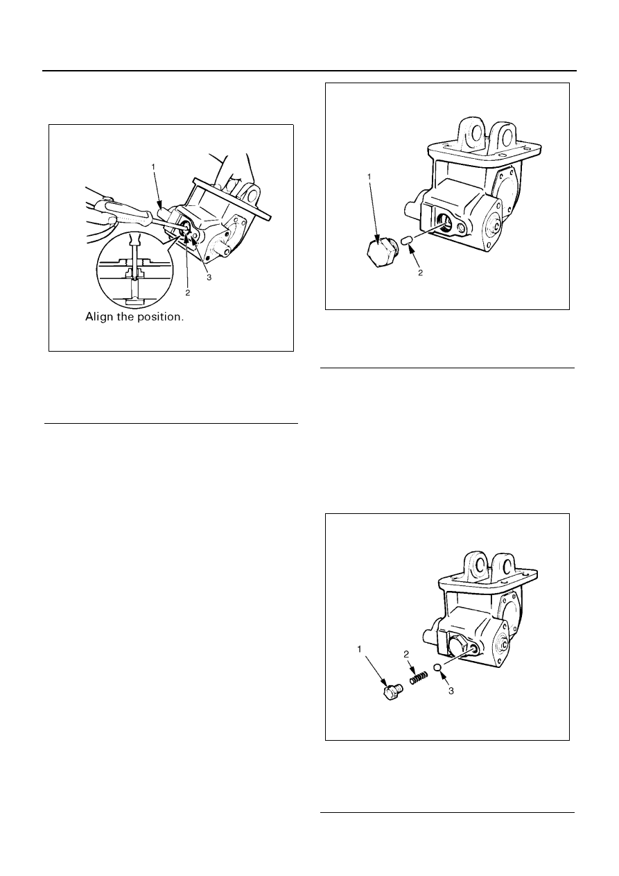
9. Ball
10. Spring
11. Spring Set Bolt
• Assemble the ball and spring in the gear case
and coat the spring set bolt threaded portion
with liquid gasket (LOCTITE 242 or equivalent),
then tighten the spring set bolt.
Tighten:
Set bolt to 19 N
⋅m (1.9 kg⋅m / 14 lb⋅ft)
12. Output Gear
Legend
1. Shift rod
2. Shift arm
3. Alignment mark
NPA0123E
Legend
1. Interlock plug
2. Interlock pin
Legend
1. Spring set bolt
2. Spring
3. Ball
NPA0124E
NPA0125E