Isuzu engine 4j series. Service manual - part 87
6D3 – 6 CHARGING SYSTEM
3. Harness Connector (A/C Model)
•
Disconnect the "L", "S", "IG" terminal.
•
Disconnect the "B" terminal.
4. Vacuum Hose (EXH. Brake Model)
•
Remove the vacuum hose to vacuum tank and
exhaust actuator.
5. Oil Hose
•
Remove the oil hose from oil pan.
•
Remove the oil hose of vacuum pump side.
6. AC Generator Drive Belt
•
Loosen the adjust plate fixing bolt.
•
Remove the adjust bolt.
•
Loosen the AC Generator fixing bolt then remove the
fan belt.
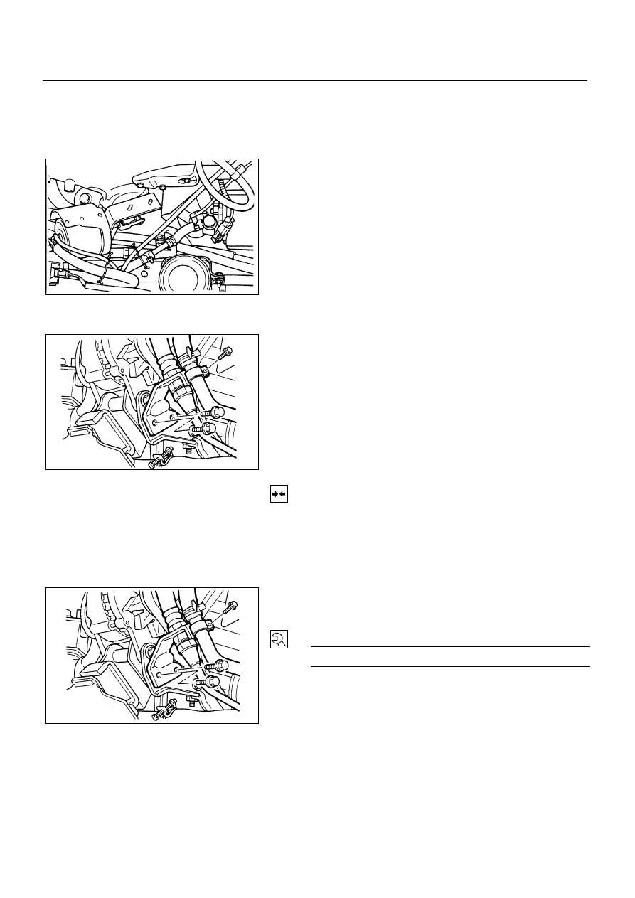
7. Power Steering Oil Pipe Bracket (P/S Model)
•
Remove the oil pressure pipe bracket fixing bolt and
pipe clip bolt.
•
Remove the oil suction pipe clip bolt.
8. AC Generator Fixing Bolts
9. AC Generator Assembly
INSTALLATION
9. AC Generator Assembly
•
Set the AC generator.
8. AC Generator Fixing Bolts
•
Temporary install the AC generator fixing bolt.
7. Power Steering Oil Pipe Bracket (P/S Model)
•
Install the oil pipe bracket and tighten bolts to the
specified torque.
Pipe Bracket Bolt torque
N∙m (kg∙m/lb∙ft)
19 (1.9/14)
6D3-6-1.tif
6D3-6-2.tif
6D3-6-3.tif