Isuzu engine 4j series. Service manual - part 72


  Index      Isuzu     Isuzu engine 4j series - manual


Search            


Content   ..  70  71  72  73   ..


Isuzu engine 4j series. Service manual - part 72


6C - 32  ENGINE FUEL

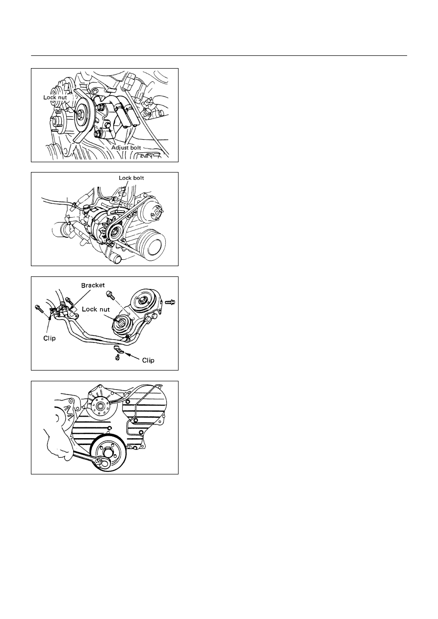
4. A/C Compressor Drive Belt (A/C Model)

Loosen A/C compressor idler pulley lock nut, adjust
bolt, and remove the drive belt.

5. AC Generator Drive Belt

Loosen AC generator mounting bolt (under side) and
adjust plate lock bolt, and remove the drive belt.

6. Power Steering Pump & Bracket Assembly (P/S Model)

Loosen power steering oil pipe bracket and clip.

Remove P/S pump bracket assembly and hang the
P/S pump bracket assembly.

7. Crankshaft Dumper Pulley

6C-31-1.tif

6C-31-2.tif

6C-31-3.tif

6C-31-4.tif

ENGINE FUEL  6C - 33

8. Timing Pulley Upper Cover

9. Timing Pulley Lower Cover

10. Flange; Camshaft Pulley

11. Timing Belt

Prepare a fixing bolt (M8 x 40, P=1.25)

Turn crankshaft timing pulley in the normal direct
pulley side mark to timing pulley housing side mark.

Make sure that the camshaft pulley and injection
timing pulley fixing bolt holes are set to each other.
Then Fit in a fixing bolt and lightly tighten.

No. 1 cylinder should be at top dead center.
If the fixing bolt holes are not set (No. 4 cylinder is at
top dead center) give another turn.

Remove tensioner and timing belt.

WARNING

If crankshaft and camshaft and turned with timing
belt being not mounted, piston and valve will
interfere with each other.  Therefore, the shafts
must not be turned.

6C-32-1.tif

6C-32-2.tif

6C-32-4.tif

6C-32-3.tif

6C - 34  ENGINE FUEL

12. Injection Pump Timing Pulley

Install the stopper bolt 

!

 to the timing pulley to

prevent it from turning.

Use the timing pulley puller 

"

 to remove the injection

pump timing pulley.
Timing Pulley Puller: 5-8840-0086-0

Remove the stopper bolt.

13. Air Intake Duct

14. Injection Pump Control Cable

Remove the control cable bracket bolt and remove the
control lever side.

15.  Fuel Hose

Disconnect the fuel feed hose and fuel return hose.

16. CSD Water Hose

17. Injection Pump Harness

18. Injection Pipe

19. Injection Pump Assembly

Remove the pump bracket bolt engine side.

Remove the adjust lock bolt.

Remove the injection pump fixing bolt and take out
injection pump.

6C-33-1.tif

6C-33-2.tif

6C-33-3.tif

ENGINE FUEL  6C - 35

INSTALLATION

19.  Injection Pump Assembly

Put the timing pulley housing side and injection pump
side setting marks together, and temporarily tighten.

After adjusting injection timing retighten.

Mount rear bracket on cylinder block and tighten to the
specified torque.

N∙m (Kg∙m/lb∙ft)


19 (1.9/14)


Install adjust lock bolt and lightly tighten.

After adjusting injection timing, retighten.

18. Injection Pipe

 Connect the pump side and nozzle side of the pipe,
and tighten securely.

Install clip where it was.

Sleeve Nut Torque

N∙m (Kg∙m/lb∙ft)


29 (3.0/22)


17. Injection Pump Harness

Mount engine harness and connect it to switches.

16. CSD Water Hose

Connect the water hose and tighten clip securely.

15. Fuel Hose

Connect the fuel feed hose and fuel return hose.

Connect the rear off hose.

14. Injection Pump Control Cable

1) Install the Control wire to the engine control lever.
2) Hold the accelerator lever 

!

 in the fully closed

position and stretch the control cable 

"

 in the

direction indicated by the arrow to remove any slack.

3) Tighten the accelerator cable bracket bolt.

6C-34-1.tif

6C-34-2.tif

6C-34-3.tif

6C-34-4.tif


Content   ..  70  71  72  73   ..