Isuzu engine 4j series. Service manual - part 20
6A – 16
GENERAL ENGINE MECHANICAL
REASSEMBLY
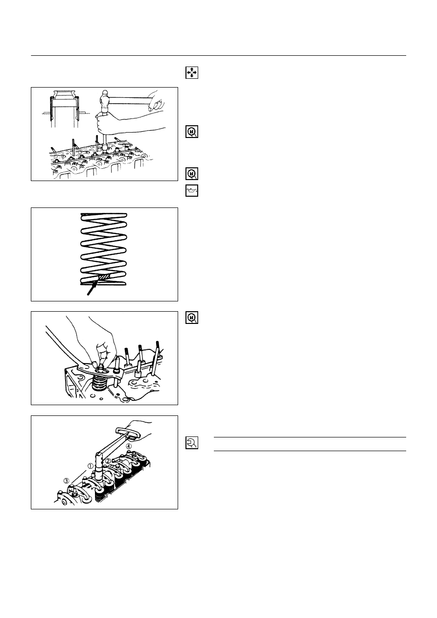
6. Valve Guide
•
Apply engine oil to the outside of the valve guide.
Using special tool, drive in a new valve guide from the
rocker arm shaft side.
Valve guide replacer: 9-8523-1212-0
5. Valve Guide Oil Seal
•
Using special tool, drive in a new oil seal
Oil special tool, drive in a new oil seal
Oil seal installer: 5-8840-2033-0
4. Valve
•
Apply engine oil to the outside of the valve stem.
3. Valve Spring
•
Attach the valve seat to the upper spring seat. The
painted area of the valve spring should be facing
downward.
2. Split Collar
•
Use a spring compressor to push the valve spring into
position.
•
Install the spring seat split collar.
•
Set the split collar by tapping lightly around the head of
the collar with a rubber hammer.
Valve spring compressor: 9-8523-1423-0 (J-29760)
1. Rocker Arm Assembly
N∙m (kg∙m/lb∙ft)
54 (5.5/40)
6A-16-1.tif
6A-16-2.tif
6A-16-3.tif
6A-16-4.tif