Harley Davidson 2008 Touring Models. Service Manual - page 35


  Главная      Harley Davidson     Harley Davidson 2008 Touring Models. Service Manual


Search            copyright infringement  


Content      ..     33      34      35      36     ..


Harley Davidson 2008 Touring Models. Service Manual - page 35


7.

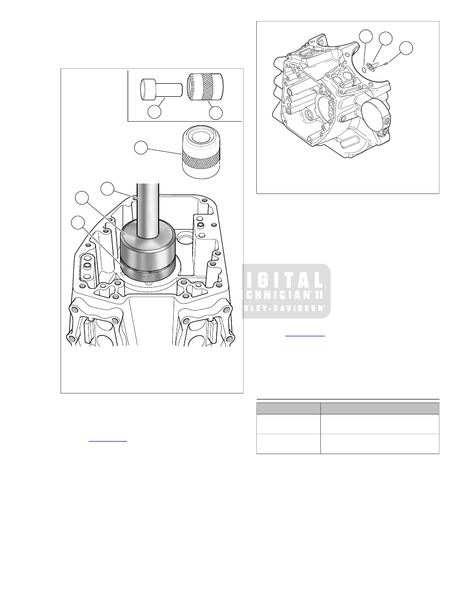
Center pilot/driver under ram (3) of press. Apply pressure
to pilot/driver until resistance is felt and bearing is bot-
tomed on the support tube.

8.

Remove pilot/driver and crankcase half from support tube.

4

1

3

2

1

5

sm02304

1.

Pilot/driver

2.

Support tube

3.

Ram

4.

Main bearing

5.

Support tube (2) "B" end up

Figure 3-125. Right Main Bearing Installation

Piston Jets Removal

1.

See 

Figure 3-126

. Remove two T20 TORX screws (1) to

free piston jet (2) from crankcase.

2.

Remove o-ring (3) from groove in mounting flange of jet.
Discard o-ring.

1

2

3

sm02305

1.

T20 TORX screw

2.

Piston jet

3.

O-ring

Figure 3-126. Piston Jets

Piston Jets Installation

NOTES

If piston jet is being reused, apply LOCTITE THREAD-
LOCKER 222 (purple) to threads of TORX screws before
installation.

O-rings that are missing, distorted, pinched or otherwise
damaged will result in either oil leakage or low oil pressure.
Use of the wrong o-ring will have the same results. Since
many o-rings are similar in size and appearance, always
use new o-rings keeping them packaged until use to avoid
confusion.

1.

See 

Figure 3-126

. Apply a very thin film of clean H-D

20W50 engine oil to new o-ring (3) for piston jet. Install
new o-ring in groove of jet mounting flange.

2.

With jet pointed upward, start two T20 TORX screws (1)
to secure piston jet (2) to crankcase. Tighten to 25-35 in-
lbs
 (2.8-3.9 Nm).

LEFT CRANKCASE HALF

TOOL NAME

PART NUMBER

CRANKCASE BEARING
REMOVER/INSTALLER

B-45655

CRANKCASE BEARING
REMOVER/INSTALLER BASE

HD-42720-5

Main Bearing Removal

NOTE

Never move or lift the crankcase by grasping the cylinder studs.
The crankcase is too heavy to be carried in this manner and
could be dropped.

2008 Touring Service:  Engine  3-91

Do not rotate left crankcase half in engine stand such that
flywheel sprocket shaft is facing up.The flywheel assembly
can fall out, resulting in parts damage or moderate injury.
(00552b)

1.

While holding flywheel assembly so that it does not fall
out of left crankcase half, rotate bottom end assembly in
engine stand so assembly is upright and flywheel shafts
are horizontal.

2.

Carefully slide flywheel assembly out of left crankcase and
place it in a clean safe place.

3.

Unbolt left crankcase half from stand and move it to bench
area. Remove thrust washer from outboard side of crank-
case half by pulling it past oil seal. Set thrust washer aside
for inspection or reuse.

4.

Remove oil seal from crankcase bore. Discard oil seal.

5.

See 

Figure 3-127

. Obtain CRANKCASE BEARING

REMOVER/INSTALLER (Part No. B-45655) and
CRANKCASE BEARING REMOVER/INSTALLER
BASE (Part No. HD-42720-5).

6.

Place support tube on work bench with "B" end up. Note
that the sides of the support tube are stamped "A" and "B"
to indicate proper orientation. With inboard side of left
crankcase half facing upward, position main bearing bore
over support tube.

7.

See 

Figure 3-128

. The left main bearing (1) is press-fit

into the main bearing bore (2) in the left crankcase and
secured with a retaining ring (3) on the inboard side. See

Figure 3-129

. Using the tip of a flat blade screwdriver,

carefully lift the edge of the retaining ring up out of its
groove in the crankcase. Slide the screwdriver tip around
the edge of the bearing, lifting the retaining ring up and
out of the groove. Be careful not to damage the lip of the
groove in the crankcase.

1

2

sm02307

1.

Support tube

2.

Pilot/driver

Figure 3-127. Left Main Bearing Remover and Installer

Tools

1

2

3

sm02522

1.

Main bearing

2.

Main bearing bore

3.

Retaining ring

Figure 3-128. Left Main Bearing Assembly

sm02523

Figure 3-129. Removing Retaining Ring

3-92  2008 Touring Service:  Engine

3

1

3

2

sm02524

1.

Ram

2.

Pilot/driver

3.

Support tube ("A" end up)

Figure 3-130. Left Main Bearing Removal

8.

See 

Figure 3-130

. Place support tube (3) on hydraulic

press table with the "A" end up. Note that the sides of the
support tube are stamped "A" and "B" to ensure proper
orientation.

9.

With the outboard side of the left crankcase half facing
upward, position main bearing bore over support tube.

10. Slide pilot/driver (2) through main bearing into support

tube.

11. Center pilot/driver under ram (1) of press. Apply pressure

to pilot/driver until bearing is free.

12. Remove crankcase half, pilot/driver and bearing from

support tube. Discard bearing.

Main Bearing Installation

NOTE

Never move or lift the crankcase by grasping the cylinder studs.
The crankcase is too heavy to be carried in this manner and
could be dropped.

1.

See 

Figure 3-127

. Obtain CRANKCASE BEARING

REMOVER/INSTALLER (Part No. B-45655) and
CRANKCASE BEARING REMOVER/INSTALLER BASE
(Part No. HD-42720-5).

1

3

4

2

3

sm02525

1.

Ram

2.

Pilot/driver

3.

Support tube ("A" end up)

4.

Main bearing

Figure 3-131. Left Main Bearing Installation

2.

See 

Figure 3-131

. Obtain new main bearing (4). Place a

thin film of clean engine oil on outer diameter of bearing.

3.

Place support tube (3) on hydraulic press table with the
"B" end up.

4.

With the inboard side of the left crankcase half facing
upward, position main bearing bore over support tube.

5.

Lubricate leading edge of new main bearing before
placement. Start new main bearing in bearing bore, letter
side down.

6.

Slide pilot/driver (2) through bearing into support tube.

7.

Center pilot/driver (2) under ram (1) of press. Apply pres-
sure to pilot/driver until bearing is lightly bottomed in main
bearing bore.

8.

Remove crankcase half and pilot/driver from support tube.

9.

Obtain new retaining ring and install in bearing bore in
inboard side of crankcase half. Work retaining ring into
groove, being careful not to damage edges of groove.
Make sure retaining ring is fully seated in groove.

NOTE

If retaining ring will not fit into groove in bearing bore, it is a
sign that the bearing is not fully seated in the bore. Examine
the bearing and bore. If necessary, remove bearing, clean bore
and reinstall bearing. Then install retaining ring.

2008 Touring Service:  Engine  3-93

SPROCKET SHAFT BEARING INNER RACE

TOOL NAME

PART NUMBER

ROBINAIR HEAT GUN

HD-25070

MAINSHAFT BEARING INNER RACE
PULLER/INSTALLER

HD-34902-B

FLYWHEEL SUPPORT FIXTURE

HD-44358

WEDGE ATTACHMENT

HD-95637-46B

SPROCKET SHAFT BEARING
INSTALLER

HD-97225-55C

Removal

If reusing flywheel, remove bearing inner race and thrust
washer as follows:

1.

Obtain FLYWHEEL SUPPORT FIXTURE (Part No. HD-
44358). See 

Figure 3-132

. Install brass jaws or shop

towels around teeth of vise to prevent damage to tool.
Clamp tool in vise with the round hole topside.

2.

Insert crankshaft end through hole resting flywheel
assembly on fixture. Slide knurled locating pin down slot
in tool to engage crank pin hole. Hand tighten locating pin.

3.

Slide hold-down clamp down slot to engage inboard side
of right flywheel half, and then hand tighten knurled nut at
bottom to secure. Repeat step to secure hold-down clamp
on opposite side of flywheel.

NOTE

For proper clamping force, hold-down clamp must not be tilted.
Rotate hex on outboard stud until clamp is level.

1

2

sm03852

1.

Locating pin

2.

Hold-down clamp

Figure 3-132. Flywheel Fixture (Part No. HD-44358)

4.

Position WEDGE ATTACHMENT (Part No. HD-95637-
46B) on inboard side of thrust washer and turn hex nuts
an equal number of turns to draw halves of wedge
together.

Install wedge attachment only so far as necessary to
ensure positive contact with bearing inner race. Installing
tool with more contact than necessary will result in damage
to the flywheel (00500b)

5.

Obtain two 3/8-16 inch bolts 7-1/2 inches long (with flat
washers). Install flat washers on bolts. Obtain bridge and
forcing screw from MAINSHAFT BEARING INNER RACE
PULLER/INSTALLER (Part No. HD-34902-B). Also obtain
a suitable hardened washer to use between the puller
screw and the end of the shaft.

6.

Slide one bolt into channel on each side of bridge so that
flat washer is between bridge and bolt head. Thread bolts
into wedge attachment an equal number of turns.

7.

Sparingly apply graphite lubricant to threads of forcing
screw to prolong service life and ensure smooth operation.
Start forcing screw into center hole of bridge.

NOTE

Failure to use hardened washer may result in damage to forcing
screw and/or sprocket shaft.

8.

Place hardened washer against end of sprocket shaft.
Thread forcing screw into bridge until the steel ball at the
end of the screw makes firm contact with hardened
washer.

9.

Using the ROBINAIR HEAT GUN (Part No. HD-25070),
uniformly heat the bearing inner race for about 30 seconds
using a circular motion.

NOTE

To facilitate removal without heat, apply a light penetrating oil
to shaft and leading edge of bearing inner race.

Do not use heating devices with penetrating oil. Penet-
rating oil is flammable which could result in death or ser-
ious injury. (00375a)

10. Turn forcing screw until thrust washer and bearing inner

race move approximately  1/8 in. (3.2 mm).

11. Turn hex nuts an equal number of turns to separate halves

of WEDGE ATTACHMENT (Part No. HD-95637-46B).

12. After bottoming thrust washer on shaft, reposition WEDGE

ATTACHMENT (Part No. HD-95637-46B) on inboard side
of bearing inner race. Turn hex nuts an equal number of
turns to draw halves of wedge together.

Install wedge attachment only so far as necessary to
ensure positive contact with bearing inner race. Installing
tool with more contact than necessary will result in damage
to the flywheel (00500b)

13. See 

Figure 3-133

. Verify that the tool assembly is square,

so that the bearing inner race is not cocked during
removal.

14. Using the ROBINAIR HEAT GUN (Part No. HD-25070),

uniformly heat the bearing inner race for about 30 seconds
using a circular motion.

NOTE

To facilitate removal without heat, apply a light penetrating oil
to shaft and leading edge of bearing inner race.

15. Turn forcing screw until bearing inner race is pulled free

of sprocket shaft.

3-94  2008 Touring Service:  Engine

16. Remove thrust washer from sprocket shaft.

2

1

3

7

6

5

4

sm03853

1.

Forcing screw

2.

3/8-16 in. bolt with flat washer

3.

Bridge

4.

Hardened washer

5.

Wedge attachment

6.

Bearing inner race

7.

Sprocket shaft

Figure 3-133. Remove Inner Race from Sprocket Shaft

Installation

1.

Place new thrust washer over sprocket shaft.

2.

Place new bearing inner race on bench top. Using the
ROBINAIR HEAT GUN (Part No. HD-25070), uniformly
heat bearing inner race for about 60 seconds using a cir-
cular motion.

3.

Wearing suitable gloves to protect hands from burns, place
heated bearing inner race over sprocket shaft.

NOTE

To facilitate installation without heat, apply a light penetrating
oil to shaft and leading edge of bearing inner race.

Do not use heating devices with penetrating oil. Penet-
rating oil is flammable which could result in death or ser-
ious injury. (00375a)

4.

See 

Figure 3-134

. Obtain the SPROCKET SHAFT

BEARING INSTALLER (Part No. HD-97225-55C).
Assemble tool as described below.

a.

See 

Figure 3-135

. Thread pilot adapter into sprocket

shaft.

b.

Thread pilot shaft onto pilot adapter.

c.

Slide long collar over pilot shaft until it contacts
bearing inner race.

d.

Slide short collar over pilot shaft until it contacts long
collar.

e.

Slide Nice bearing and large flat washer over pilot
shaft.

f.

Sparingly apply graphite lubricant to threads of pilot
shaft to prolong service life and ensure smooth oper-
ation.

g.

See 

Figure 3-136

.Thread handle onto pilot shaft.

5.

See 

Figure 3-137

. Rotate handle of tool in a clockwise

direction until bearing inner race makes firm contact with
thrust washer. Verify that thrust washer cannot be rotated
by hand.

6.

Remove handle, flat washer, Nice bearing, short collar,
long collar, pilot shaft and pilot adapter from sprocket shaft.

sm03854

Figure 3-134. Sprocket Shaft Bearing Installer (Part No.

HD-97225-55C)

sm03855

Figure 3-135. Thread Pilot Adapter into Sprocket Shaft

2008 Touring Service:  Engine  3-95

1

2

3

4

5

6

7

8

9

sm03856

1.

Pilot adapter

2.

Pilot shaft

3.

Handle

4.

Flat washer

5.

Nice bearing

6.

Short collar

7.

Long collar

8.

Inner race

9.

Thrust washer

Figure 3-136. Press Inner Race onto Sprocket Shaft: Setup

sm03857

Figure 3-137. Press Inner Race onto Sprocket Shaft:

Operation

CYLINDER STUDS

Removal

1.

Thread a 3/8"-16 nut onto cylinder stud.

2.

Thread a second nut onto stud until it contacts the first.

3.

Placing wrench on first nut installed, remove stud.

Installation

1.

Place a steel ball inside a head screw. Put the head screw
on the end of the cylinder stud without the collar.

2.

Start the stud in the cylinder deck with the collar side down.
Tighten using air gun until collar reaches crankcase.

3.

Hand tighten stud to 10-20 ft-lbs (3.6-27.1 Nm).

3-96  2008 Touring Service:  Engine

PIPE PLUG AND OIL FITTINGS

Removal

See 

Figure 3-138

Turn pipe plug counterclockwise until free.

sm02309

Figure 3-138. Pipe Plug

Installation

1.

Apply LOCTITE PIPE SEALANT 565 to threads.

2.

Install pipe plug. Tighten pipe plug to 120-144 in-lbs (13.6-
16.3 Nm).

CLEANING AND INSPECTION

1.

Scrape old gasket material from the crankcase flanges.
Old gasket material left on mating surfaces will cause
leaks.

2.

Clean all parts in a non-volatile cleaning solution or
solvent.

Compressed air can pierce the skin and flying debris from
compressed air could cause serious eye injury. Wear
safety glasses when working with compressed air. Never
use your hand to check for air leaks or to determine air
flow rates. (00061a)

3.

Blow parts dry with low pressure compressed air.

4.

Verify that all oil holes and passageways are clean and
open.

5.

Check ring dowels for looseness, wear or damage.
Replace as necessary.

6.

Use a file to carefully remove any nicks or burrs from
machined surfaces.

7.

Clean out tapped holes and clean up damaged threads.

8.

Check the top of the crankcase for flatness with a
straightedge and feeler gauge. Replace if warped.

9.

Spray all machined surfaces with clean engine oil.

INSTALLATION OVERVIEW

1.

Perform all steps under 

3.18 BOTTOM END OVERHAUL:

ASSEMBLY

.

2.

Perform all steps under 

3.16 TOP END OVERHAUL:

ASSEMBLY

.

2008 Touring Service:  Engine  3-97

3.28

FLYWHEEL AND CONNECTING RODS

REMOVAL OVERVIEW

1.

Perform all steps under 

3.15 TOP END OVERHAUL:

DISASSEMBLY

.

2.

Perform all steps under 

3.17 BOTTOM END OVERHAUL:

DISASSEMBLY

.

INSPECTION

NOTE

Do not attempt to straighten connecting rods. Straightening
rods will damage both the upper bushing and lower bearing.

1.

Replace the flywheel/connecting rod assembly if any of
the following conditions are noted:

a.

Connecting rods are bent or twisted.

b.

Connecting rods do not fall under their own weight or
are in a bind.

c.

Sprocket teeth are worn in an irregular pattern or
chipped.

d.

The crankshaft (roller) bearing inner races are
brinelled, burnt, scored, blued or damaged.

NOTE

Bluing on connecting rods is part of the hardening process and
is considered a normal condition.

2.

Check connecting rod bearing clearance. Orient the
assembly as shown in 

Figure 3-139

.

a.

Holding the shank of each rod just above the bearing
bore, pull up and down on the connecting rods.

b.

Any discernible up and down movement indicates
excessive lower bearing clearance. Replace the fly-
wheel/connecting rod assembly.

3.

See 

Figure 3-140

. Check connecting rod side play.

a.

Insert a feeler gauge between the thrust washer and
the outboard side of the connecting rod.

b.

Replace the assembly if rod side play exceeds  0.020
in. (0.51 mm).

NOTE

If the flywheel, connecting rods or right side bearing inner race
need to be replaced, then replace the entire flywheel assembly.

sm02310

Figure 3-139. Connecting Rod Bearing Clearance

sm02311

Figure 3-140. Connecting Rod Side Play

INSTALLATION OVERVIEW

1.

Perform all steps under 

3.18 BOTTOM END OVERHAUL:

ASSEMBLY

.

2.

Perform all steps under 

3.16 TOP END OVERHAUL:

ASSEMBLY

.

3-98  2008 Touring Service:  Engine

3.29

OIL PAN

REMOVAL

1.

Position motorcycle on a suitable lift.

2.

See 

Figure 3-141

. Drain fluids.

a.

Remove engine oil drain plug, fill plug/dipstick and oil
filter. Drain oil into suitable container. See

1.5 ENGINE OIL AND FILTER

.

b.

Remove transmission drain plug. Drain transmission
fluid into suitable container. See 

1.10 TRANSMIS-

SION LUBRICANT

.

3.

Remove rear wheel. See 

2.4 REAR WHEEL

.

4.

See 

Figure 3-141

. Remove 12 screws (4) that secure the

oil pan to the transmission.

NOTES

Use holes in lower frame crossmember to access some
of the screws.

Verify engine oil fill plug/dipstick is removed before
attempting to slide the oil pan rearward. Contact with the
oil pan will result in damage to the dipstick.

5.

Slide oil pan (8) rearward to remove. Remove and discard
oil pan gasket (3).

6.

Remove serpentine baffle (2) and baffle springs (1) from
oil pan.

1

2

3

4

5

7

8

6

sm03674

5.

1.

Transmission drain plug and o-ring

Baffle spring (2)

2.

6.

Serpentine baffle

Pipe plug

7.

3.

Engine oil drain plug and o-ring

Oil pan gasket

4.

8.

Screw (12)

Oil pan

Figure 3-141. Oil Pan Assembly: Touring Models

INSTALLATION

1.

See 

Figure 3-141

. Clean and examine transmission and

oil pan flanges.

2.

Apply a thin coat of HYLOMAR

®

 gasket sealer to oil pan

flange.

3.

Place new gasket (3) on oil pan flange. Allow sealer to
dry until tacky.

4.

Install serpentine baffle (2) and baffle springs (1) in oil
pan.

2008 Touring Service:  Engine  3-99

5.

Position gasket and oil pan at bottom of transmission.
Install 12 screws (4), but only tighten about two turns after
initial engagement.

NOTE

It is normal for the baffle springs to hold the oil pan away from
the transmission. Use a long screwdriver to compress the
springs as necessary. Exercise caution to avoid cocking or
distorting the springs.

6.

Inspect the oil pan gasket to ensure that it is properly
positioned. If gasket has shifted out of position, remove
screws and adjust as necessary.

7.

Alternately tighten the oil pan screws to 84-132 in-lbs (9.5-
14.9 Nm) following sequence shown in 

Figure 3-142

.

8.

Install drain plugs.

a.

Wipe any foreign material from engine and transmis-
sion drain plugs.

b.

Examine drain plug o-rings for tears or damage.
Replace o-rings as required.

c.

Install transmission drain plug and o-ring. Tighten to
14-21 ft-lbs (19.0-28.5 Nm).

d.

Install engine oil drain plug and o-ring. Tighten to 14-
21 ft-lbs (19.0-28.5 Nm).

9.

Install rear wheel. See 

2.4 REAR WHEEL

10. Add fluids.

a.

Add transmission fluid and check level. See

1.10 TRANSMISSION LUBRICANT

.

b.

Install engine oil filter. Add engine oil and check level.
See 

1.5 ENGINE OIL AND FILTER

.

11

9

3

2

6

8

5

1

4

10

12

7

sm03673

Figure 3-142. Oil Pan Torque Sequence

3-100  2008 Touring Service:  Engine

SUBJECT

............................................................................................................................

PAGE NO.

4.1 SPECIFICATIONS: FUEL SYSTEM..........................................................................................4-1
4.2 ELECTRONIC FUEL INJECTION (EFI)....................................................................................4-2
4.3 AIR CLEANER ASSEMBLY.......................................................................................................4-3
4.4 FUEL TANK...............................................................................................................................4-5
4.5 FUEL TANK TOP PLATE...........................................................................................................4-9
4.6 FUEL FILTER..........................................................................................................................4-12
4.7 FUEL PRESSURE REGULATOR............................................................................................4-13
4.8 FUEL LEVEL SENDER...........................................................................................................4-14
4.9 TWIST GRIP SENSOR............................................................................................................4-15
4.10 THROTTLE CONTROL ACTUATOR (TCA)...........................................................................4-19
4.11 ENGINE TEMPERATURE SENSOR (ET).............................................................................4-20
4.12 INDUCTION MODULE..........................................................................................................4-21
4.13 MANIFOLD ABSOLUTE PRESSURE SENSOR (MAP)........................................................4-24
4.14 OXYGEN SENSORS (O2).....................................................................................................4-25
4.15 FUEL INJECTORS................................................................................................................4-27
4.16 FUEL PUMP..........................................................................................................................4-29
4.17 FUEL PRESSURE TEST.......................................................................................................4-31
4.18 EXHAUST SYSTEM..............................................................................................................4-33
4.19 ACTIVE EXHAUST (HDI)......................................................................................................4-39
4.20 INTAKE LEAK TEST..............................................................................................................4-40
4.21 EVAPORATIVE EMISSIONS CONTROL (CA MODELS)......................................................4-42

FUEL SYSTEM

4.1

SPECIFICATIONS: FUEL SYSTEM

SPECIFICATIONS

Table 4-1. Fuel Capacity: 2008 Touring Models

LITERS

GALLONS

FUEL TANK CAPACITY

22.7

6.0

Total

3.79

1.0

Reserve (warning light
on)

2008 Touring Service:  Fuel System  4-1

4.2

ELECTRONIC FUEL INJECTION (EFI)

TROUBLESHOOTING

See the ELECTRICAL DIAGNOSTIC MANUAL for
troubleshooting and diagnostic information.

4-2  2008 Touring Service:  Fuel System

4.3

AIR CLEANER ASSEMBLY

REMOVAL

1.

See 

Figure 4-1

. Remove screw from air cleaner cover.

Remove air cleaner cover with rubber seal.

2.

Remove three T27 TORX screws to release cover bracket
from filter element.

3.

Remove filter element pulling two breather tubes from
holes on inboard side.

4.

Remove gasket from sleeve on inboard side of filter ele-
ment. Discard gasket.

5.

Remove breather tubes from fittings on two cylinder head
breather bolts.

6.

Remove two cylinder head breather bolts from backplate.

7.

Remove backplate from cylinder heads.

8.

Remove seal ring from groove on inboard side of back-
plate. Discard seal ring.

Do not use gasoline or solvents to clean filter element.
Flammable cleaning agents can cause an intake system
fire, which could result in death or serious injury. (00101a)

9.

Inspect filter element. See 

1.7 AIR CLEANER AND

EXHAUST SYSTEM

. Replace the filter element if damaged

or if filter media cannot be adequately cleaned.

INSTALLATION

1.

With the nubs contacting the ring groove walls, install seal
ring on inboard side of backplate.

2.

Align holes in backplate with those in cylinder heads and
install cylinder head breather bolts. Alternately tighten
bolts to 22-24 ft-lbs (29.8-32.5 Nm).

3.

Slide new gasket over sleeve on inboard side of filter
element.

4.

Insert breather tubes about  0.25 inch (6.4 mm) into holes
on inboard side of filter element.

5.

Install breather tubes onto fittings of two cylinder head
breather bolts.

NOTE

Air cleaner mounting without installation of the breather tubes
allows crankcase vapors to be vented into the atmosphere in
violation of legal emissions standards.

6.

Place filter element onto backplate with the flat side down.

7.

Align holes in cover bracket with those in filter element
and start three T27 TORX screws. Alternately tighten
screws to 40-60 in-lbs (4.5-6.8 Nm).

8.

Verify that rubber seal is properly seated around perimeter
of air cleaner cover.

9.

Fit air cleaner cover into backplate. Apply a small dab of
LOCTITE MEDIUM STRENGTH THREADLOCKER 243
(BLUE) to threads of cover screw. Install screw and tighten
to 36-60 in-lbs (4.1-6.8 Nm).

2008 Touring Service:  Fuel System  4-3

5

6

1

2

7

3

4

8

9

10

11

12

sm04085

7.

1.

Filter element

Cover screw

2.

8.

Cover trim

Gasket

9.

3.

Breather tube (2)

Air cleaner cover

4.

10.

Rubber seal

Breather bolt (2)

11.

5.

Backplate

T27 Torx screw (3)

6.

12.

Cover bracket

Seal ring

Figure 4-1. Air Cleaner Assembly

4-4  2008 Touring Service:  Fuel System

4.4

FUEL TANK

GENERAL

Stop the engine when refueling or servicing the fuel
system. Do not smoke or allow open flame or sparks near
gasoline. Gasoline is extremely flammable and highly
explosive, which could result in death or serious injury.
(00002a)

The fuel tank is treated to resist rusting. However, when the
motorcycle is not operated for a long period of time, see

1.24 STORAGE

 for specific information regarding fuel tank

treatment.

REMOVAL

NOTE

The fuel tank can be removed without draining. However,
draining is necessary whenever the fuel tank or internal com-
ponents are serviced.

To prevent spray of fuel, purge system of high-pressure
fuel before supply line is disconnected. Gasoline is
extremely flammable and highly explosive, which could
result in death or serious injury. (00275a)

NOTE

The gasoline in the fuel supply line is under high pressure: 58
psi (400 kPA). To avoid an uncontrolled discharge or spray of
gasoline, always purge the line before disconnecting.

1.

Purge the fuel supply line as follows:

a.

Remove left side saddlebag. See 

2.27 SADDLE-

BAGS

.

b.

Remove left side cover.

c.

Remove 15 amp fuel pump fuse. See 

Figure 4-2

.

d.

Start the engine and allow the motorcycle to run.

e.

When the engine stalls, operate starter for 3 seconds
to remove remaining fuel from fuel supply line.

f.

Remove maxi-fuse.

g.

Reinstall 15 amp fuel pump fuse.

2.

Remove seat. See 

2.26 SEAT

.

3.

Remove console. Proceed as follows:

a.

Remove socket screw to release front of console from
fuel tank weldment.

b.

Remove hex screw to release rear console bracket
from clip nut on rear fuel tank bracket.

c.

Lay a clean shop towel on forward part of rear fender.

d.

FLHR/C: Remove console and lay upside down on
shop towel.

e.

FLHX, FLHT/C/U, FLTR: Press button to open fuel
door on console. Remove filler cap. Remove console
and lay upside down on shop towel. Install filler cap.

4.

Gently pry fuel vapor vent tube from vapor valve fitting on
top plate.

5.

Remove fuel level sender/fuel pump connector [141], 4-
place Delphi.

6.

On FLHR/C models, move to bottom left side of fuel tank.
Gently pull on convoluted tubing to draw fuel gauge con-
nector [117], 4-place Multilock, out of tunnel at front of fuel
tank. Disconnect connector.

Gasoline can drain from the fuel line when disconnected
from fuel tank. Gasoline is extremely flammable and highly
explosive, which could result in death or serious injury.
Wipe up spilled fuel immediately and dispose of rags in a
suitable manner. (00260a)

7.

Locate quick-connect fitting on left side of fuel tank. Pull
up on chrome sleeve and pull down on fuel supply line
fitting to disconnect. See 

Figure 4-3

.

8.

Remove rubber caps to reveal two front fuel tank screws.
Remove screws to release flanges from frame bosses.

9.

Remove plastic trim cover over rear fuel tank bracket.
Remove two screws to release bracket from frame back-
bone.

NOTE

The fuel tank screws have both a T40 TORX recess and an
external hex. Use of an open end/box wrench on the external
hex allows the front screws to be removed without having to
loosen or remove the fairing lowers, if installed.

10. Remove fuel tank from motorcycle.

2008 Touring Service:  Fuel System  4-5


Content      ..     33      34      35      36     ..