Harley Davidson 1986-2003 XL/XLH Sportster. Service Manual - page 27
1. Disconnect the negative battery cable as described in
this chapter.
2. Disconnect the connector housing.
3. Remove the secondary locking wedge as follows:
a. Locate the secondary locking wedge in Figure 194 or
Figure 195.
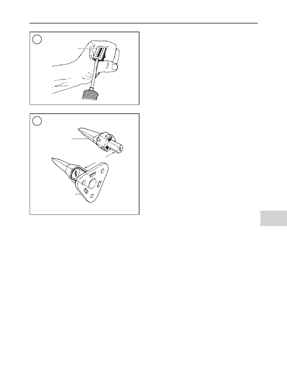
b. Insert a wide-blade screwdriver between the socket
housing and the locking wedge. Turn the screwdriver
90
°
to force the wedge up (Figure 196).
c. Remove the secondary locking wedge.
4. Press the terminal latches inside the socket housing and
remove the socket terminal through the holes in the rear
wire seal.
5. Repeat Step 3 for each socket terminal.
6. If necessary, remove the wire seal.
7. Install the wire seal into the socket housing if it was re-
moved.
8. Hold onto the socket housing and insert the socket ter-
minals through the holes in the wire seal so they enter the
correct chamber hole. Continue until the socket terminal
locks into place. Then lightly tug on the wire to make sure it
is locked into place.
9. Set the internal seal onto the socket housing if it was re-
moved.
NOTE
With the exception of the 3-pin Deutsch con-
nector, all of the secondary locking wedges
are symmetrical. When assembling the 3-pin
connector, install the connector so the arrow
on the secondary locking wedge is pointing
toward the external latch as shown in
Figure
197.
NOTE
If the secondary locking wedge does not slide
into position easily, one or more of the socket
terminals are not installed correctly. Correct
the problem before trying to lock the wedge
into the socket.
10. Install the secondary locking wedge into the socket
housing as shown in Figure 194 or Figure 195. Press the
secondary locking wedge down until it locks into place.
Pin terminal removal/installation
This procedure is shown on a 12-pin Duetsch connector
and relates to all of the Deutsch connectors.
Refer to Figure 194 and Figure 195.
1. Disconnect the negative battery cable as described in
this chapter.
2. Disconnect the connector housing.
3. Use needlenose pliers to remove the locking wedge.
4. Lightly press the terminal latches inside the pin housing
and remove the pin terminal(s) through the holes in the rear
wire seal.
5. Repeat Step 3 for each socket terminal.
6. If necessary, remove the wire seal.
7. Install the wire seal into the socket housing if it was re-
moved.
8. Hold onto the pin housing and insert the pin terminals
through the holes in the wire seal so they enter their correct
chamber hole. Continue until the pin terminal locks into
place. Then lightly tug on the wire to make sure it is locked
into place.
NOTE
With the exception of the 3-pin Deutsch con-
nector, all of the secondary locking wedges
are symmetrical. When assembling the 3-pin
connector, install the connector so the arrow
on the secondary locking wedge is pointing
toward the external latch as shown in
Figure
197
.
NOTE
If the locking wedge does not slide into posi-
tion easily, one or more of the pin terminals are
not installed correctly. Correct the problem
before trying to lock the wedge into the socket.
ELECTRICAL SYSTEM
459
12
196
Secondary
locking wedge
197
Pin housing
Arrows point to
external latch
Socket housing