Harley Davidson 1986-2003 XL/XLH Sportster. Service Manual - page 13


  Главная      Harley Davidson     Harley Davidson 1986-2003 XL/XLH Sportster. Service Manual


Search            copyright infringement  


Content      ..     11      12      13      14     ..


Harley Davidson 1986-2003 XL/XLH Sportster. Service Manual - page 13


Engine Oil and Filter Change

Table 1 lists the recommended oil and filter change inter-

vals for motorcycles operated in moderate climates. If the
motorcycle is operated in heavy dust, mud, water or other
conditions, the oil should be changed more frequently.

The manufacturer recommends using Harley-Davidson

oils. If not available, the manufacturer recommends using oil
certified for use in diesel engines. Acceptable certifications
include: CF-4, CG-4, CH-4 and CI-4. Follow the viscosity
recommendations applicable to Harley-Davidson oil.

Always use the same brand of oil at each change. Refer to

Table 3 for the correct oil viscosity to use in anticipated ambi-
ent temperatures, not engine oil temperature. Using oil addi-
tives is not recommended as they may cause the clutch to slip.

WARNING

Contact with oil may cause skin cancer. Wash
oil from hands with soap and water a soon as
possible after handling engine oil.

CAUTION

Do not use the current SH and SJ rated auto-
motive oils in motorcycle engines. The SH
and SJ rated oils contain friction modifiers
that reduce frictional losses on engine com-
ponents. Specifically designed for automotive
engines, these oils can damage motorcycle
engines and clutches.

1. Run the motorcycle until the engine has reached normal
operating temperature. Turn the engine off and allow the oil
to settle in the oil tank. Support the motorcycle so that the
oil can drain completely.
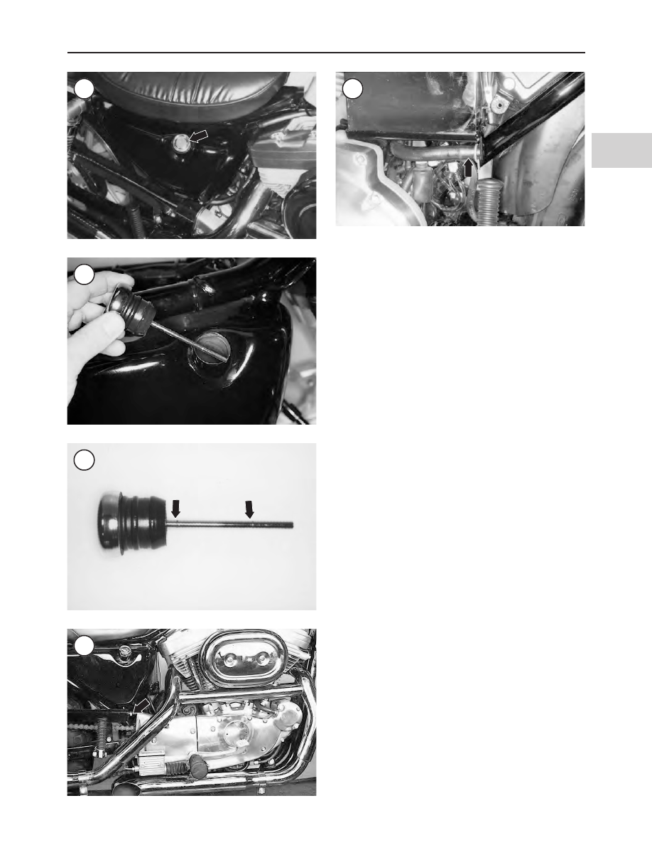
2. Wipe the area around the oil filler cap (Figure 5) with a
clean rag. Remove the cap by pulling up.
3. Locate the oil drain hose.

a. On 1986-1990 models, the oil drain hose extends

from the bottom of the oil tank (Figure 8).

b. On 1991-1993 models, the drain hose (Figure 9) is se-

cured to the battery tray lug on the left side of the
motorcycle.

c. On 1994-2003 models, the drain hose is secured to a

lug on the rear muffler mount on the left side of the
motorcycle (Figure 10).

LUBRICATION, MAINTENANCE AND TUNE-UP

117

3

5

6

7

8

9

4. Place a drain pan underneath the oil tank drain line.
5. Detach the hose clamp, then direct the hose end into the
drain pan.
6. Allow the oil to drain completely. Remove the oil tank
filler cap (Figure 5) for faster oil flow.
7. Reattach the oil drain hose and clamp.
8. To replace the oil filter, perform the following:

a. Place a drain pan underneath the front portion of the

crankcase and the oil filter.

b. Install a suitable oil filter wrench (Figure 11)

squarely onto the oil filter and loosen it counterclock-
wise. Quickly remove the oil filter as oil will begin to
run out of it.

c. Hold the filter over the drain pan and pour out the re-

maining oil. Place the filter in a plastic bag, seal the
bag and dispose of it properly.

d. Wipe off all oil that drained onto the engine. Clean

with a contact cleaner to eliminate all oil residue from
the engine prior to installing the new oil filter.

e. Pour approximately 4 oz. (120 ml) of new engine oil

into the new oil filter. Allow the oil to soak into the
filter element.

f. Coat the gasket on the new filter (Figure 12) with

clean oil.

CAUTION

Tighten the oil filter by hand. Do not
overtighten.

g. Screw the oil filter onto the mounting pad by hand

and tighten it until the filter gasket touches the seal-
ing surface, then tighten the filter by hand an addi-
tional 1/2 to 3/4 turn.

CAUTION

Do not overfill the oil tank. Oil may be forced
into the air cleaner causing engine malfunc-
tion or damage.

9. Add the correct viscosity (Table 3) and quantity (Table
4
) of oil to the oil tank–minus the 4 oz. (120 ml) poured into
the oil filter.

CAUTION

On 1994-2003 models, perform Step 10 to
prevent oil pump cavitation.

10. On 1994-2003 models, remove air from the oil tank
drain hose using the following procedure:

a. Place a drain pan under the oil tank drain hose.
b. Detach the hose clamp, then direct the hose end into

the drain pan.

c. Allow a small amount of oil to drain out of the hose.
d. Reattach the oil drain hose and clamp.

11. Install the oil tank filler cap.
12. Run the engine at idle speed. The oil pressure warning
light should go out when engine speed is 1000 rpm or
higher. If not, shut off the engine and determine the cause.

118

CHAPTER THREE

10

Pipe elbow

Oil feed/drain
hose

Oil feed hose
(to oil pump inlet)

Front

Pipe tee

Oil drain hose

Rear muffler mount

Clamp

11

12

On 1986-1990 models, if the warning light remains on per-
form the following:

a. Stop the engine.
b. Remove the oil tank filler cap.
c. Loosen the lower, front oil pump hose fitting (Figure

13) and allow 2 oz. (60 ml) of oil to drain out.

d. Tighten the fitting and install the oil tank filler cap.
e. Run the engine to verify the warning light goes out.

13. Check for oil leaks, particularly at the oil filter and
drain hose.
14. Stop the engine.
15. Check the oil level on the dipstick as described in this
section.
16. Properly dispose of the used oil.

Transmission Oil

CAUTION

Do not fill the transmission with engine oil.
Only add the recommended transmission oil
in

Table 5

. Overfilling may cause clutch mal-

functioning.

The transmission oil also lubricates the clutch, primary

drive chain and sprockets.

Table 1 lists the recommended transmission oil inspec-

tion intervals. When checking the transmission oil level, do
not allow any dirt or debris to enter the transmission case
opening.

Oil level check
(1986-1990 models)

1. If the motorcycle has been operated recently, wait ap-
proximately ten minutes before checking the oil to allow
the oil to settle in the case. Park the motorcycle on a level
surface and have an assistant support it so that it is standing
straight up.

CAUTION

Do not check the oil level with the motorcycle
supported on the sidestand or the reading will
be incorrect.

2. Place a drain pan beneath the primary chain cover.
3. Remove the oil level plug from the bottom of the cover
(A, Figure 14).
4. Oil should seep from the plug hole. If not, remove the
access cover from the top of the primary chain cover (B,
Figure 14). Slowly add the recommended oil (Table 5)
through the access cover hole until oil begins to run out of
the oil level plug hole. When the oil just seeps out of the
hole, install the oil level plug.
5. Install the access cover (B, Figure 14).

Oil level check
(1991-1993 models)

1. If the motorcycle has been operated recently, wait ap-
proximately ten minutes before checking the oil to allow
the oil to settle in the case. Park the motorcycle on a level
surface and have an assistant support it so that it is standing
straight up.

CAUTION

Do not check the oil level with the motorcycle
supported on the sidestand or the reading will
be incorrect.

2. Place a drain pan beneath the primary chain cover.
3. Remove the oil level plug from the bottom, rear of the
cover (Figure 15).

LUBRICATION, MAINTENANCE AND TUNE-UP

119

3

13

14

15

4. Oil should seep from the plug hole. If not, remove the
access cover from the primary chain cover (Figure 16).
Slowly add the recommended oil (Table 5) through the ac-
cess cover hole until oil begins to run out of the oil level
plug hole. When the oil just seeps out of the hole, install the
oil level plug.
5. Install the access cover (Figure 16).

Oil level check
(1994-2003 models)

1. If the motorcycle has been operated recently, wait ap-
proximately ten minutes before checking the oil to allow
the oil to settle in the case. Park the motorcycle on a level
surface and have an assistant support it so that it is standing
straight up.

CAUTION

Do not check the oil level with the motorcycle
supported on the sidestand or the reading will
be incorrect.

2. Clean the area around the clutch inspection cover (Fig-
ure 17
).

NOTE

If a suitable tool is not available to remove
the lower, left cover screw, remove the footrest
(Chapter Sixteen).

3. Remove the clutch inspection cover retaining screws,
then remove the cover.

NOTE

The primary drive cover is removed in

Figure

18

for clarity. It is not necessary to remove the

cover.

4. Check the transmission oil level through the primary
drive cover opening (A, Figure 19). It should be even with
the bottom of the clutch diaphragm spring (Figure 18).
5. If the oil level is low, add the recommended type of
transmission oil listed in Table 5. Do not overfill.
6. Be sure the quad ring is located in the primary drive
cover groove (B, Figure 19).
7. Install the inspection cover so the notch in the cover
(Figure 20) fits over the cable boss (C, Figure 19) on the
primary drive cover. Tighten the primary drive cover re-
taining screws to 84-108 in.-lb. (10-12.0 N•m).

Transmission oil change
(1986-1993 models)

Table 1 lists the recommended transmission oil change

intervals.
1. Ride the motorcycle for approximately ten minutes and
shift through all five gears until the transmission oil has
reached normal operating temperature. Turn off the engine

and allow the oil to settle in the case. Park the motorcycle
on a level surface and have an assistant support it so that it
is standing straight up.

2. Place a drain pan underneath the engine and remove the
oil drain plug (Figure 21).

3. Inspect the drain plug O-ring (Figure 22) for damage
and replace it if necessary.

4. The drain plug is magnetic. Check the plug for metal de-
bris that may indicate transmission damage, then wipe off
the plug. Replace the plug if it is damaged.

5. Install the drain plug and O-ring and tighten to 14-21
ft.-lb. (19-28 N•m).

120

CHAPTER THREE

16

17

Clutch inspection cover

18

6A. On 1986-1990 models, remove the access cover (B,
Figure 14) and refill with the recommended quantity (Ta-
ble 4
) and type (Table 5) transmission oil.
6B. On 1991-1993 models, remove the inspection cover
(Figure 16) and refill with the recommended quantity (Ta-
ble 4
) and type (Table 5) transmission oil.
7. Check the oil level as described in this section.

Transmission oil change
(1994-2003 models)

Table 1 lists the recommended transmission oil change

intervals.
1. Ride the motorcycle for approximately ten minutes and
shift through all five gears until the transmission oil has
reached normal operating temperature. Turn off the engine
and allow the oil to settle in the case. Park the motorcycle
on a level surface and have an assistant support it so that it
is standing straight up.
2. Place a drain pan underneath the engine and remove the
oil drain plug (Figure 21).
3. Inspect the drain plug O-ring (Figure 22) for damage
and replace it if necessary.
4. The drain plug is magnetic. Check the plug for metal de-
bris that may indicate transmission damage, then wipe off
the plug. Replace the plug if it is damaged.
5. Install the drain plug and O-ring and tighten to 14-21
ft.-lb. (19-28 N•m).
6. Clean the area around the clutch inspection cover (Fig-
ure 17
).
7. Remove the clutch inspection cover retaining screws,
then remove the cover (Figure 17).

NOTE

The primary drive cover is removed in

Figure

18

for clarity. It is not necessary to remove the

cover.

8. Refill the transmission through the opening in the pri-
mary drive cover with the recommended quantity (Table 4)
and type (Table 5) of transmission oil. The transmission oil
level should be even with the bottom of the clutch dia-
phragm spring (Figure 19).
9. Install the clutch inspection cover. Tighten the retaining
screws to 84-108 in.-lb. (10-12.0 N•m).
10. Check the oil level as described in this section.

Fork Oil Change

This procedure is for a fork oil change. If the fork has

been disassembled for service, refer to Chapter Fourteen
for fork oil refilling and specifications.

Table 1 lists the recommended fork oil change intervals.

CAUTION

Do not allow the fork oil to come in contact
with the brake components.

LUBRICATION, MAINTENANCE AND TUNE-UP

121

3

20

Notch

21

22

19

1. Place a drain pan beside one fork tube, then remove the
drain screw (Figure 23) from the slider.
2. Straddle the motorcycle and apply the front brake lever.
Push down on the fork and release. Repeat to force as much
oil out of the fork tube and slider as possible.
3. Repeat Steps 1-2 for the opposite fork tube.
4. After the fork oil has thoroughly drained, install the
drain screw (Figure 23) onto the fork slider. Tighten the
drain screw securely.
5. Support the front of the motorcycle so the front wheel is
off the ground.

WARNING

The fork cap is under spring pressure and
may fly off when loosening it. In addition,
make sure the fork tube is fully extended from
the slider. If the fork is damaged and stuck in
a compressed state, the fork should be disas-
sembled by a dealer, as the fork cap and
spring will fly out from the fork tube under
considerable force when the cap is removed.

CAUTION

Use only a 6-point socket to loosen and
tighten the fork tube cap to avoid cosmetic
damage to the fork tube cap. Using a 12-point
socket may round off the corners of the fork
tube cap.

6. Remove the fork cap from the top of the fork tube (Fig-
ure 24
).
7. Refill each fork leg with the correct viscosity (Table 5)
and quantity of fork oil (Table 6).
8. Repeat Step 6 and Step 7 for the opposite fork tube.
9. Replace the fork cap O-ring (Figure 25, typical) if leak-
ing, excessively worn or damaged.

NOTE

It takes considerable pressure to push the fork
cap down against spring pressure while turn-
ing it.

10. Attach a suitable socket to a speed wrench, then push
down on the speed wrench to turn the fork cap. It may be
necessary to move aside the handlebar and lower handlebar
holder (Chapter Fourteen) so the socket will fit properly on
the fork cap. A fork spring compression kit is available
from Motion Pro.
11. Install the fork cap (Figure 24) onto the top of the fork
tube. Tighten the fork cap securely.
12. Road test the motorcycle and check for leaks.

Control Cables (Non-Nylon Lined Cables)

Lubricate the control cables with a cable lubricant at the

intervals in Table 1, or when they become stiff or sluggish.
When lubricating the control cables, inspect each cable for
fraying and cable sheath damage. Replace damaged cables.

CAUTION

If the original equipment cables have been re-
placed with nylon-lined cables, do not lubri-
cate them as described in this procedure. Oil
and most cable lubricants will cause the ca-
ble liner to expand, pushing the liner against
the cable sheath. Nylon-lined cables are nor-
mally used dry. When servicing nylon-lined
and other aftermarket cables, follow the man-
ufacturer’s instructions.

CAUTION

Do not use chain lubricant to lubricate con-
trol cables.

122

CHAPTER THREE

23

24

25

CAUTION

The starting enrichment valve (choke) cable
is designed to operate with a certain amount
of cable resistance. Do not lubricate the en-
richment cable or its conduit.

1A. Disconnect the clutch cable ends as described in

Clutch

Cable

in Chapter Six or Chapter Seven.

1B. Disconnect both throttle cable ends as described in the

Throttle and Idle Cables

in Chapter Ten or Chapter Eleven.

2. Attach a lubricator tool (Figure 26) to the cable follow-
ing the tool manufacturer’s instructions. Place a shop cloth
at the end of the cable to catch excess lubricant.

3. Apply lubricant until it begins to flow out of the other
end of the cable. If the lubricant squirts out from around the

lubricator, it is not clamped to the cable properly. Loosen
and reposition the cable lubricator.

CAUTION

If the lubricant does not flow out of the other
end of the cable, check the cable for fraying,
bending or other damage. Replace damaged
cables.

4. Remove the lubricator tool and wipe off both ends of the
cable.
5A. Reconnect the clutch cable ends as described in

Clutch

Cable

in Chapter Six or Chapter Seven.

5B. Reconnect both throttle cable ends as described in

Throttle and Idle Cable

in Chapter Ten or Chapter Eleven.

6. Adjust the cables as described in this chapter.

Throttle Control Grip Lubrication

Table 1 lists the recommended throttle control grip lubri-

cation intervals. To remove and install the throttle grip, re-
fer to the

Throttle and Idle Cable Replacement

section in

ChapteTen or Chapter Eleven. Lubricate the throttle con-
trol grip where it contacts the handlebar with graphite.

Front Brake Lever Pivot Pin Lubrication

Inspect the front brake lever pivot pin (Figure 27) at the

intervals in Table 1. If the pin is dry, lubricate it with a
lightweight oil. To service the pivot pin, refer to the

Front

Master Cylinder

section in Chapter Sixteen.

Clutch Lever Pivot Pin Lubrication

Inspect the clutch lever pivot pin (Figure 28) at the inter-

vals in Table 1. Lubricate the pin with a lightweight oil. To
service the pivot pin, refer to the

Clutch Cable Replacement

in Chapter Six or Chapter Seven.

Drive Chain Lubrication

Lubricate the drive chain on appropriate models so

equipped at the interval indicated in Table 1.
1. The manufacturer recommends the following lubricants
depending on the chain type:

a. On models equipped with a standard drive chain, use

H-D Chain Spray or H-D High-Performance Chain
Lube.

b. On models equipped with an O-ring drive chain, use

H-D High-Performance Chain Lube or an automo-
tive lubricant rated API GL-5 with a viscosity index
of SAE 80 or 90.

NOTE

On an O-ring type drive chain, the chain lu-
brication described in this procedure is used
mainly to keep the O-rings pliable and to pre-

LUBRICATION, MAINTENANCE AND TUNE-UP

123

3

26

27

28

vent the side plates and rollers from rusting.
The actual chain lubrication is enclosed
within the chain by the O-rings.

2. Ride the motorcycle a few miles to warm the drive
chain. A warm chain increases lubricant penetration.
3. Park the motorcycle on level ground. Support the motor-
cycle securely on a swing arm stand with the rear wheel off
the ground.
4. Oil the bottom chain (Figure 29) with a suitable chain
lubricant. Concentrate on getting the oil down between the
side plates on both sides of the chain. Do not over lubricate.
5. Rotate the chain and continue lubricating until the entire
chain has been covered.
6. Turn the rear wheel slowly and wipe off excess oil from
the chain. Also wipe off lubricant from the rear hub, wheel
and tire.
7. Remove the auxiliary stand.

Sidestand Lubrication

Refer to Table 1 for the specified lubrication interval for

the sidestand. Lubricate the bushings using wheel bearing
grease, then reassemble the sidestand. Refer to Chapter
Seventeen

Steering Head Lubrication

Refer to Table 1 for the specified lubrication interval for

the steering head bearings. Refer to Chapter Fourteen and
disassemble the steering head as needed for access to the
bearings. Lubricate the bearings using wheel bearing
grease, then reassemble the steering head.

Speedometer Cable Lubrication
(1986-1994 Models)

Lubricate the cable annually or whenever the speedome-

ter needle operates erratically.
1. Disconnect the speedometer fitting from the back of the
speedometer (Figure 30).
2. Pull the cable from the cable housing.
3. Clean off the old lubricant.
4. Apply speedometer cable lubricant to the cable.
5. Install the cable into the housing. Turn the cable so it en-
gages the drive unit at the lower end. When the cable stops
turning, the lower end is properly engaged.
6. Reconnect the upper end to the speedometer.

PERIODIC MAINTENANCE

Perform the services listed at the intervals in Table 1. If

the motorcycle is exposed to harsh condition, perform the
services more frequently.

Primary Chain Adjustment

1. Disconnect the negative battery cable as described in
Chapter Twelve.

2. Support the motorcycle on a stand or floor jack with the
rear wheel off the ground. Refer to

Motorcycle Stands

in

Chapter Thirteen.

3A. On 1986-1990 models, unscrew the primary chain in-
spection cover (Figure 31).

3B. On 1991-2003 models, remove the retaining bolts, then
remove the primary chain inspection cover (Figure 32).

4. Turn the primary chain to find the tightest point on the
chain. Measure chain free play at this point.

124

CHAPTER THREE

29

30

31

5. Check primary chain free play at the upper chain run
midway between the sprockets (Figure 33). If the primary
chain free play is incorrect, continue with Step 6. If the free
play is correct, go to Step 7. The primary chain free play
specifications are:

a. Cold engine: 3/8-1/2 in. (9.6-12.7 mm).
b. Hot engine: 1/4-3/8 in. (6.4-9.6 mm).

6. To adjust the chain, perform the following:

a. Loosen the primary chain adjuster locknut (A, Fig-

ure 34, typical).

b. Rotate the adjuster (B, Figure 34) to obtain the de-

sired chain free play.

c. Tighten the primary chain adjuster locknut (A, Fig-

ure 34) to 98-144 in.-lb. (10.8-16.3 N•m) on
1986-1990 models or 20-25 ft-lb. (28-34 N•m) on
1991-2003 models.

d. Recheck free play.

NOTE

If specified primary chain free play cannot be
obtained using the adjuster, the primary
chain or adjuster mechanism is excessively
worn and should be removed for inspection.
Refer to Chapter Six or Chapter Seven.

7. Reinstall the primary chain inspection cover and O-ring.
8. Lower the motorcycle to the ground.

Drive Chain (Models So Equipped)

Adjustment

Check and adjust the drive chain at the intervals specified

in Table 1. If the motorcycle is operated at sustained high
speeds or if it is repeatedly accelerated very hard, inspect
the drive chain adjustment more often. The correct amount
of drive chain free play (Figure 35), when pushed up mid-
way on the lower chain run (with the rider seated), is listed
in Table 7.

When adjusting the chain, check the free play at several

places along its length by rotating the rear wheel. The chain
rarely wears uniformly and as a result will be tighter at
some places than others. Measure the chain free play half-
way between the sprockets (Figure 35). Make sure the
chain free play at the tightest place on the chain is not less
than the specification in Table 7.
1. Turn the engine off and shift the transmission into neutral.

NOTE

As drive chains stretch and wear, the chain
will become tighter at one point. The chain
must be checked and adjusted at this point.

2. Turn the rear wheel slowly, then stop it and check the
chain tightness. Continue until the tightest point is lo-
cated. Mark this spot and turn the wheel so that the mark is
located on the lower chain run, midway between both
drive sprockets.

LUBRICATION, MAINTENANCE AND TUNE-UP

125

3

32

33

34

35

NOTE

If the drive chain is kinked or feels tight, it
may require cleaning and lubrication. Clean
and lubricate the primary chain as described
in this section.

3. Have a rider on the seat.
4. Push the chain up midway between the sprockets and
measure the chain free play (Figure 35).
5. If the chain free play is incorrect, adjust it as described in
the following steps.
6. On 1989-2003 models, remove and discard the rear axle
cotter pin (A, Figure 36).
7. Loosen the rear axle nut (B, Figure 36).
8. Turn the adjuster locknuts (C, Figure 36) on both sides
of the wheel. Turn both adjuster nuts an equal number of
turns to obtain the correct drive chain free play. Proceed as
follows to check wheel alignment.
9A. On 1986-1990 models, check rear wheel alignment as
follows:

a. Sight along the drive chain as it runs over the rear

driven sprocket. It should leave the driven sprocket in
a straight line as shown in A, Figure 37.

b. If the drive chain is cocked to one side or the other (B

or C, Figure 37), turn the adjuster locknuts as needed
to obtain a straight chain run and correct chain free
play.

9B. On 1991 models, check rear wheel alignment as fol-
lows:

a. Using a suitable metal rod, construct the tool shown

in Figure 38.

b. Insert the end of the tool into the index hole in the

swing arm (A, Figure 39).

c. Slide the rubber grommet along the tool until it aligns

with the center of the axle (B, Figure 39).

d. Check alignment on the opposite side, comparing the

rubber grommet position with the center of the axle.
The alignment on both sides of the axle must be the
same. If necessary, adjust the axle with the axle ad-
justers, while at the same time maintaining correct
drive chain free play.

10. Tighten the rear axle nut to 60-65 ft. (81-88 N•m). On
1989-1991 models install a new rear axle cotter pin (A, Fig-
ure 36
).
11. Tighten the chain adjuster locknuts securely.

Inspection

1. Clean the drive chain as described in this section
2. Park the motorcycle on level ground. Support the motor-
cycle securely with the rear wheel off the ground.
3. At the rear sprocket, pull one of the links away from the
driven sprocket. If the link pulls away more than 1/2 the
height of the sprocket tooth (Figure 40), the chain is exces-
sively worn.

4. Inspect the inner plate chain faces (Figure 41). They
should be polished on both sides. If they show uneven wear,
the sprockets are not aligned properly.

5. Inspect the drive and driven sprockets for the following
defects:

a. Undercutting or sharp teeth (Figure 42).

b. Broken teeth.

6. Check the drive sprocket nut and the driven sprocket
nuts for looseness. Refer to Chapter Thirteen.

126

CHAPTER THREE

36

37

38

Steel or brass rod

Rubber grommet

7. If excessive chain or sprocket wear is evident, replace
the chain and both sprockets as a complete set (Chapter
Thirteen).

Cleaning

1. Remove the drive chain as described in Chapter
Thirteen.

CAUTION

Only kerosene should be used to clean
O-ring drive chains. Do not use gasoline,
solvent or paint thinner. Do not steam clean
the chain.

2. Immerse the chain in a pan of cleaning solvent and allow
it to soak for about a half hour. Move it around and flex it
during this period so the dirt between the pins and rollers
can work out.
3. Scrub the rollers and side plates with a stiff brush and
rinse away loosened dirt. Rinse the chain a couple of times
to make sure all debris is washed out. Hang up the chain and
allow it to thoroughly dry.

NOTE

Do not allow a chain to remain dry and
unlubricated for an extended period, other-
wise, rust may occur.

4. Clean any dirt or grit off the sprockets.
5. Install the chain as described in Chapter Thirteen.
6. Lubricate the chain as described in this chapter.

Final Drive Belt

Deflection

Check drive belt deflection at the intervals in Table 1. If

the drive belt is severely worn, or if it is wearing incor-
rectly, refer to Chapter Thirteen for inspection and replace-
ment procedures.

NOTE

Check the drive belt deflection when the belt
is cold.

1. Support the motorcycle on a stand or floor jack with the
rear wheel off the ground. Refer to the

Motorcycle Stands

section in Chapter Thirteen.
2. Turn the rear wheel and check the drive belt for its tight-
est point. Mark this point. Turn the wheel so the tight spot is
on the lower belt run, midway between the sprockets.
3. Lower the motorcycle to the ground.
4. Position the motorcycle so both wheels are on the
ground without a rider or cargo on the motorcycle.
5. Observe the belt position through the window in the de-
bris deflector (Figure 43). Mark the position of the belt.

LUBRICATION, MAINTENANCE AND TUNE-UP

127

3

39

40

1/2 tooth

41

Roller pin (inner plate) Pin link

Pin

Roller

Bushing

42

Normal wear

Excessive wear

NOTE

Use a belt tension gauge (A,

Figure 44

) (part

No. HD-35381-A

or equivalent) to apply

pressure against the drive belt in Step 6. A
suitable equivalent is the Yamaha belt tension
tool (B,

Figure 44

).

NOTE

Be sure the belt tension gauge is positioned so
it applies force squarely against the belt.

6. Apply a force of 10 lb. (4.5 kg) to the middle of the
lower belt strand (Figure 45) and make another mark on the
debris deflector to indicate the position of the deflected
belt.

7. Note the number of graduations between the marks.
Each graduation next to the window equals 1/8 in. (3.2
mm). Calculate the amount of belt deflection and refer to
Table 7 for the correct specification. Adjust the belt as de-
scribed in this section.

Adjustment

1. Measure the belt deflection as described in in this sec-
tion.

2. On the left side, remove the cotter pin (A, Figure 36)
and loosen the rear axle nut (B).

3. Turn the adjuster locknut (C, Figure 36) on each side, in
either direction, an equal number of turns to obtain the cor-
rect drive belt deflection.

CAUTION

The rear wheel must be properly aligned with
the chassis so the drive belt runs true on the
front and rear sprockets. A misaligned rear
wheel will cause uneven, rapid drive belt
wear.

4. Check that the rear axle is positioned correctly within
the swing arm as follows:

a. Using a suitable metal rod, construct the tool shown

in Figure 38.

b. Insert the end of the tool into the index hole in the

swing arm (A, Figure 39).

c. Slide the rubber grommet along the tool until it aligns

with the center of the axle (B, Figure 39).

d. Check alignment on the opposite side, comparing the

rubber grommet position with the center of the axle.
The alignment on both sides of the axle must be the
same. If necessary, adjust the axle with the axle ad-
justers (Figure 46), while at the same time maintain-
ing correct drive belt deflection.

5. Tighten the rear axle nut to 60-65 ft.-lb. (81-88 N•m)
and install a new cotter pin.

6. Recheck the drive belt deflection. Tighten the adjuster
locknuts securely.

128

CHAPTER THREE

43

44

45

Belt deflection

10 lbs. (4.5 kg)

46

Brake Pad Inspection

NOTE

It may be necessary to dismount the caliper in
the following steps if there is not sufficient ac-
cess to the brake pads. Refer to Chapter
Sixteen.

1. Inspect the brake pads for damage.
2. Measure the thickness of each brake pad lining on the
front caliper(s) (Figure 47) and rear caliper (Figure 48).
Replace the brake pad if its thickness is worn to the mini-
mum thickness (Figure 49) as listed in Table 7. Replace the
brake pads as described in Chapter Sixteen.

Brake Fluid Level Inspection

WARNING

If the reservoir is empty, air has probably en-
tered the brake system. Bleed the breaks as
described in Chapter Sixteen.

WARNING

Only use DOT 5 brake fluid. Do not use brake
fluid labeled DOT 5.1. This is a glycol-based
fluid that is not compatible with sili-
cone-based DOT 5. DOT 5 fluid is purple
while DOT 5.1 fluid is amber/clear. Do not in-
termix these different types of brake fluid as it
can cause brake component damage and lead
to brake system failure.

WARNING

Do not intermix DOT 3, DOT 4 or DOT 5.1
brake fluids as they are not silicone-based.
Using non-silicone brake fluid in the models
covered in this manual can cause brake fail-
ure.

NOTE

Low brake fluid levels usually indicated
brake pad wear. As the pads wear and be-
come thinner, the brake caliper pistons auto-
matically extend farther out of their bores. As
the caliper pistons move out, the brake fluid
level drops in the system. However, if the
brake fluid level is low and the brake pads are
not worn excessively, check the system for
leaks.

Front brake (1986-1995 models)

1. Move the handlebar so the front master cylinder is
level.

NOTE

The sight glass on the side of the master cylin-
der (

Figure 50

) only provides a quick means

to determine if the brake fluid level is low, not
whether the reservoir is full.

LUBRICATION, MAINTENANCE AND TUNE-UP

129

3

47

48

49

Backing
plate

Friction
material

Minimum thickness

2. Brake fluid should be visible in all of the sight glass (A,
Figure 50).
3. Clean the top of the master cylinder.
4. Remove the screws securing the cover. Remove the cover
and diaphragm.
5. The brake fluid level should be 1/8 inch (3.2 mm) below
the top of the reservoir. If the brake fluid level is low, con-
tinue with Step 6. If the level is correct, continue with Step 7.
6. Add new DOT 5 brake fluid to raise the brake fluid level.
7. Reinstall the diaphragm and cover. Install the screws
and tighten securely.

Front brake (1996-2003 models)

1. Move the handlebar so the front master cylinder is level.
2. Look at the sight glass on top of the master cylinder
(A, Figure 51) to determine the brake fluid level. If the
fluid level is correct, the sight glass will appear dark pur-
ple. If the level is low, the sight glass will be a light color
or clear.
3. If the brake fluid level is low, add fluid as follows.
4. Clean the top of the master cylinder.
5. Remove the screws securing the cover (B, Figure 51).
Remove the cover and diaphragm.
6. The brake fluid level should be 1/8 inch (3.2 mm) below
the top of the reservoir. If the brake fluid level is low, con-
tinue with Step 7. If the level is correct, continue with Step 8.
7. Add new DOT 5 brake fluid to raise the brake fluid level.

NOTE

One side of the reservoir cover is thicker. In-
stall the cover in Step 8 so the thick side is
above the brake line fitting.

8. Reinstall the diaphragm and cover (B, Figure 51). In-
stall the screws and tighten securely.

Rear brake

1. Park the motorcycle on level ground so the motorcycle is
upright.

NOTE

The sight glass (A,

Figure 52

) on the side of

the master cylinder only provides a quick
means to determine if the brake fluid level is
low, not whether the reservoir is full.

2. Brake fluid should be visible in all of the sight glass (A,
Figure 52).
3. Clean the top of the master cylinder.
4. Remove the screws securing the cover (B, Figure 52).
Remove the cover and diaphragm.
5. The brake fluid level should be 1/8 inch (3.2 mm) below
the top of the reservoir. If the brake fluid level is low, continue
with Step 6. If the level is correct, continued with Step 7.
6. Add fresh DOT 5 brake fluid to fill the reservoir.

7. Reinstall the diaphragm and cover (B, Figure 52). In-
stall the screws and tighten securely.

Brake Disc Inspection

Inspect the front and rear brake discs for scoring, cracks

or other damage. Measure the brake disc thickness (Figure
53
) and service the brake discs as described in Chapter
Sixteen.

Brake Lines and Seals Inspection

Check the brake lines between each master cylinder and

each brake caliper. If there are any leaks, tighten the con-
nections and bleed the brakes as described in Chapter
Sixteen.

130

CHAPTER THREE

50

51

52

Brake Fluid Change

WARNING

Do not use brake fluid labeled DOT 5.1. This
is a glycol-based fluid that is not compatible
with silicone-based DOT 5. DOT 5 brake
fluid is purple while DOT 5.1 is an am-
ber/clear color. Do not intermix these differ-
ent types of brake fluid, as doing so will lead
to brake component damage and possible
brake failure.

To change brake fluid, follow the brake bleeding proce-

dure in Chapter Sixteen. Continue adding new fluid to the
master cylinder until the fluid leaving the caliper is clean
and free of contaminants and air bubbles.

Front Brake Adjustment

The front brake does not require periodic adjustment.

Rear Brake Adjustment

1986-early 1987 models

1. Sit on the motorcycle in normal riding position. Adjust
the position of the brake pedal to suit rider preference as de-
scribed in the following steps.
2. Loosen the locknuts (A, Figure 54) on the pedal adjust-
ing screw (B).
3. Turn the adjusting screw (B, Figure 54) until the desire
pedal position is obtained.

4. Tighten the locknuts (A, Figure 54) and recheck the
pedal position.
5. Push the brake pedal by hand until light resistance is felt,
which indicates the pushrod (17, Figure 55) is contacting
the piston (12).
6. Measure the gap between the adjusting screw (B, Fig-
ure 54
) and the brake pedal. The gap should be 1/16 in. (1.6
mm). If not, proceed as follows:

a. Loosen the locknut (18, Figure 55).
b. Turn the pushrod (17, Figure 55) as needed to obtain

the desired gap.

c. Tighten the locknut (18, Figure 55).

Later 1987-2003 models,
except 1999-2003 883C and 1200C models

1. Park the motorcycle on level ground so the motorcycle is
upright.
2. Note the brake pedal position with relation to the floor.
The brake pedal (Figure 56) should be parallel with the
floor.
3. Remove the cotter pin securing the clevis pin (A, Figure
57
) to the rear brake pedal. Remove the clevis pin.
4. Disconnect the brake rod end from the brake pedal.
5. Loosen the locknut (B, Figure 57) and turn the brake
rod end (C) as needed to reposition the brake pedal.
6. When the brake pedal is properly positioned, reinstall
the clevis pin and secure it with a

new

cotter pin.

1999-2003 883C and 1200C models

Refer to the

Forward Foot Controls

section in Chapter

Seventeen.

Clutch Adjustment

1986-1993 models

NOTE

The clutch cable adjuster on 1986-1987
models is located at the lower end of the ca-
ble (A,

Figure 58

). On 1988-1993 models,

the cable adjuster is located at mid-length in
the cable adjacent to the front frame down-
tube (

Figure 59

).

Refer to Figure 60 when performing this procedure.

1A. On 1986-1987 models, loosen the clutch cable jam nut
(B, Figure 58) and turn the adjuster (A) to provide maxi-
mum cable slack.
1B. On 1988-1993 models, slide the rubber boot off the
clutch in-line cable adjuster. Loosen the adjuster jam nut
(A, Figure 59) and turn the adjuster (B) to provide maxi-
mum cable slack.
2. Make sure the clutch cable ferrule seats squarely in the
lever housing receptacle (Figure 61) on the handlebar.
3. Remove the clutch inspection cover (Figure 62).

LUBRICATION, MAINTENANCE AND TUNE-UP

131

3

53

54

132

CHAPTER THREE

55

148

REAR MASTER CYLINDER

(1986-EARLY 1987 MODELS)

1. Screw
2. Cover
3. Diaphragm
4. Brake line
5. Housing
6. Lockwasher
7. Bolt
8. Spring
9. Spring seat

10. Piston cup
11. Seal
12. Piston
13. Snap ring

14. Cupped washer
15. Spring
16. Rubber boot
17. Pushrod
18. Nut
19. Rod end
20. Pin
21. Snap ring
22. Brake pedal
23. Cotter pin
24. Adjusting screw
25. Locknuts


Content      ..     11      12      13      14     ..