Mercury Grand Marquis (2011 year). Instruction - part 13
FUSES AND RELAYS
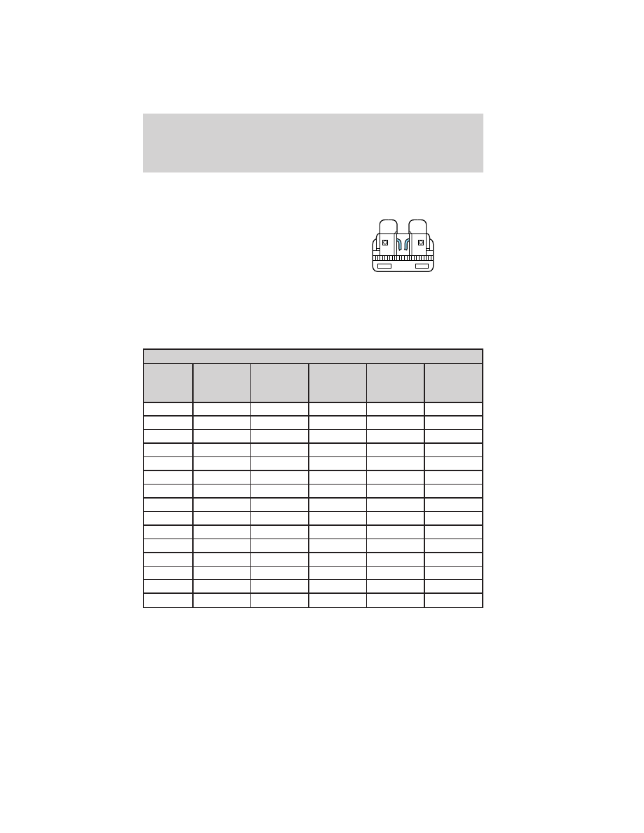
Fuses
If electrical components in the
vehicle are not working, a fuse may
have blown. Blown fuses are
identified by a broken wire within
the fuse. Check the appropriate
fuses before replacing any electrical
components.
Note: Always replace a fuse with one that has the specified amperage
rating. Using a fuse with a higher amperage rating can cause severe wire
damage and could start a fire.
Standard fuse amperage rating and color
COLOR
Fuse
rating
Mini
fuses
Standard
fuses
Maxi
fuses
Cartridge
maxi
fuses
Fuse link
cartridge
2A
Grey
Grey
—
—
—
3A
Violet
Violet
—
—
—
4A
Pink
Pink
—
—
—
5A
Tan
Tan
—
—
—
7.5A
Brown
Brown
—
—
—
10A
Red
Red
—
—
—
15A
Blue
Blue
—
—
—
20A
Yellow
Yellow
Yellow
Blue
Blue
25A
Natural
Natural
—
Natural
Natural
30A
Green
Green
Green
Pink
Pink
40A
—
—
Orange
Green
Green
50A
—
—
Red
Red
Red
60A
—
—
Blue
Yellow
Yellow
70A
—
—
Tan
—
Brown
80A
—
—
Natural
Black
Black
Passenger compartment fuse panel
The fuse panel is located below and to the left of the steering wheel by
the brake pedal. Remove the panel cover to access the fuses.
15
Roadside Emergencies
193
2011 Crown Victoria (cro)
Owners Guide, 3rd Printing
USA (fus)