Ford Mondeo (petrol engines). Manual - part 108


  Index      Ford     Ford Mondeo - service and repair manual (petrol engines)


Search            


Content   ..  106  107  108  109   ..


Ford Mondeo (petrol engines). Manual - part 108


Refitting

15 Locate the strut assembly (together with
the coil spring compressor tool) under the
wheel arch, and locate the bracket on the
bump stop on the rear suspension
crossmember. Insert the two bolts securing
the upper mounting to the underbody tower,
and tighten them to the specified torque.
16 Carefully release the coil spring
compressor tool, making sure that the spring
locates correctly in the upper and lower seats,
and that the strut bracket locates on the
crossmember bump stop. The bump stop is
tapered inwards, and the strut bracket should
be fully engaged with it before releasing the
coil spring.
17 Raise the knuckle and engage it with the
strut, then insert the clamp bolt and tighten to
the specified torque.
18 Reconnect the front and rear lower arms

to the knuckle, and finger-tighten the bolts at
this stage.
19 Reconnect the tie-bar to the bottom of the
knuckle, and finger-tighten the bolt at this
stage.
20 Refit the anti-roll bar link to the lower arm,
and tighten the nut to the specified torque.
21 On disc brake models, refit the caliper
bracket to the knuckle, and tighten the
mounting bolts to the specified torque (see
Chapter 9). Make sure that the flexible brake
hose is not twisted.
22 On drum brake models, connect the
flexible hose to the strut, insert the clip, then
insert the rigid brake line and tighten the union
nut. Remove the brake hose clamp, then
bleed the hydraulic brake circuit as described
in Chapter 9.
23 Where applicable, reconnect the wiring
multi-plug for the adaptive damping, and clip
the wiring to the strut.

24 Where applicable, refit the ABS sensor as
described in Chapter 9, and clip the wiring to
the strut.
25 Refit the wheel, and lower the vehicle to
the ground.
26 With the weight of the vehicle on the rear
suspension, fully tighten the lower arm and
tie-bar mounting bolts.

The procedure is similar to that for the front
suspension strut, and reference should be made
to Section 5. Note that the spring compressor
tools will already be in position on the coil spring
following the removal operation. Refer also to
the accompanying illustrations for details of the
separate components (see illustrations).

Removal

Chock the front wheels, then jack up the
rear of the vehicle and support it on axle
stands. Remove both rear wheels.
Unscrew the nuts securing the anti-roll bar
links to the front lower arms on both sides.
Hold the upper part of the links with a spanner
while loosening the nuts. Recover the rubber
bushes (see illustrations).

13 Rear anti-roll bar and links

(Saloon/Hatchback models) -
removal and refitting

12 Rear suspension strut

(Saloon/Hatchback models) -
overhaul

10•12 Suspension and steering systems

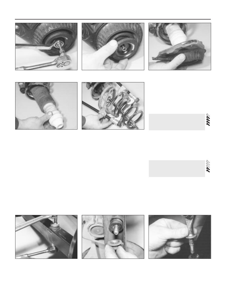
12.1A  Rear strut dismantling - unscrew

the upper mounting nut . . .

12.1B  . . . remove the cup . . .

12.1C  . . . upper mounting bracket and

seat . . .

13.2A  Loosen the nut . . .

13.2B  . . . remove the nut and rubber 

bush . . .

12.1D  . . . gaiter and bump stop . . .

12.1E  . . . and coil spring

13.2C  . . . and remove the anti-roll bar link

from the lower arm

Unscrew the bolts securing the anti-roll bar
mounting clamps to the rear suspension
crossmember, then unhook the clamps and
withdraw the anti-roll bar from under the
vehicle (see illustration).
Examine the rubber bushes for the
mounting clamps and links, and if necessary
renew them. The links are available
individually.

Refitting

Locate the anti-roll bar on the rear
crossmember, hook the mounting clamps in
position, and insert the bolts. Tighten the
bolts to the specified torque.
Locate the anti-roll bar links in the front
lower arms on both sides, making sure that
the rubber bushes are in position. Refit the
nuts and tighten them to the specified torque.
Refit the rear wheels, and lower the vehicle
to the ground.

Removal

Chock the front wheels, then jack up the
rear of the vehicle and support it on axle
stands. Remove the appropriate rear wheel.

Front lower arm

To remove the front lower arm, it is
necessary to remove the fuel tank first. Refer
to Chapter 4 for details.
Unscrew the nut and disconnect the anti-
roll bar link from the lower arm. Hold the
actual link with an adjustable spanner or grips
while unscrewing the nut, to prevent damage
to the link joint. Recover the rubber bush.
Unscrew and remove the bolt securing the
front lower arm to the knuckle.
Unscrew and remove the bolt securing the
front lower arm to the crossmember.
Withdraw the front lower arm from under
the vehicle.

Rear lower arm

Unscrew and remove the bolt securing the
rear lower arm to the knuckle.

The bolt securing the rear lower arm to the
crossmember has an eccentric head and
spacer, which are used to adjust the rear toe
setting. Before removing this bolt, mark its
position, using a scriber or similar sharp
instrument through the aperture in the
crossmember.
Unscrew and remove the bolt securing the
rear lower arm to the crossmember (see
illustration)
. The bolt may be removed
through the aperture in the crossmember.
Recover the eccentric spacer.
10 Withdraw the rear lower arm from under
the vehicle.

Refitting

11 Refitting is a reversal of the removal
procedure, but the arm mounting bolts should
be finger-tightened initially, and only fully
tightened after the vehicle is lowered to the
ground, so that its weight is on the rear
suspension. Note that the rear lower arm is
marked “TOP” for correct refitting (see
illustration)
. The rear toe setting should be
checked, and if necessary adjusted, at the
earliest opportunity.

Removal

Chock the front wheels, then jack up the
rear of the vehicle and support it on axle
stands. Remove the appropriate rear wheel.
Disconnect the handbrake cable from the
tie-bar bracket on the underbody.
Unscrew and remove the bolt securing the
tie-bar bracket to the rear suspension
knuckle.
Unscrew the bolts securing the tie-bar
bracket to the underbody, and withdraw the
bracket from the vehicle (see illustration).
Mount the bracket in a vice, then unscrew
and remove the bolt, and remove the tie-bar
from the bracket.
It is not possible to renew the rubber
bushes - if they are worn excessively, the tie-
bar should be renewed complete.

Refitting

Refitting is a reversal of the removal
procedure. The bracket-to-underbody bolts
should be fully tightened to the specified
torque before lowering the vehicle. The bolts
securing the tie-bar to the bracket and
knuckle should be finger-tightened initially,
and only fully tightened after the vehicle is
lowered to the ground, so that its weight is on
the rear suspension.

Note: Before attempting to remove the rear
suspension crossmember, tools to hold the
coil springs in compression must be obtained.
Careful use of conventional coil spring
compressors will prove satisfactory.

Removal

Chock the front wheels, then jack up the
rear of the vehicle and support it on axle
stands. Remove both rear wheels.
Remove the complete exhaust system as
described in Chapter 4.
Unscrew and remove the bolts securing the
tie-bars to the rear suspension knuckles, and
disconnect the tie-bars.
Unscrew the nuts securing the rear anti-roll
bar links to the front lower arms. Hold the

16 Rear suspension

crossmember
(Saloon/Hatchback models) 
-
removal and refitting

15 Rear suspension tie-bar

(Saloon/Hatchback models) -
removal and refitting

14 Rear suspension lower arms

(Saloon/Hatchback models) -
removal and refitting

Suspension and steering systems  10•13

10

14.11  “TOP” marking on the rear lower

arm

15.4  Tie-bar bracket on the underbody

13.3  Rear anti-roll bar mounting clamp

14.9  Bolt securing the rear lower arm to

the crossmember

actual links stationary while the nuts are being
unscrewed, to prevent damage to the joints.
Swivel the anti-roll bar upwards, and recover
the rubber bushes.
Where applicable, remove the ABS wheel
sensor from the rear suspension knuckle as
described in Chapter 9.
Unscrew and remove the bolts, and
disconnect both lower arms from the rear
suspension knuckle.
To allow the rear suspension struts to be
released from the rubber stops on the top of
the crossmember, it is necessary to fit coil
spring compressor tools to both of the rear
coil springs, and compress them until all
tension is removed from the upper and lower
mountings. 

Warning: It is important to only
use high-quality spring
compressors, and to carefully
follow the tool manufacturer’s

manuals provided with them. With the
compressor tools fitted, support the struts
to one side.
Support the rear suspension crossmember
on a trolley jack, then unscrew the four
mounting bolts from the underbody (see
illustration)
.
Lower the crossmember to the ground.
10 Unscrew the bolts securing the anti-roll
bar clamps to the crossmember, then remove
the clamps and withdraw the anti-roll bar.
11 Remove the lower arms from the
crossmember as described in Section 14.

Refitting

12 Refitting is a reversal of the removal
procedure. Ford specify the use of a special
tool (tool number 15-097) to accurately align
the crossmember onto the underbody before
tightening the mounting bolts. This tool
should be obtained if possible, since
inaccurate alignment would result in bad
handling and excessive tyre wear. The tie-bar
and arm mounting bolts should be finger-
tightened initially, and only fully tightened
after the vehicle is lowered to the ground, so
that its weight is on the rear suspension. The
rear toe setting should be checked, and if
necessary adjusted, at the earliest
opportunity.

Inspection

The rear hub bearings are non-adjustable,
and are supplied complete with the hub. It is
not possible to renew the bearings separately
from the hub.
To check the bearings for excessive wear,
chock the front wheels, then jack up the rear
of the vehicle and support it on axle stands.
Fully release the handbrake.
Grip the rear wheel at the top and bottom,
and attempt to rock it. If excessive movement
is noted, or if there is any roughness or
vibration felt when the wheel is spun, it is
indicative that the hub bearings are worn.

Renewal

Remove the rear wheel.
On drum brake models, remove the rear
brake drum as described in Chapter 9.
On disc brake models, remove the rear
brake disc as described in Chapter 9.
Turning the hub as necessary, line up the
hole in the flange with the each of the bolts
securing the hub assembly to the rear
suspension knuckle; unscrew and remove the
bolts (see illustration).
Withdraw the hub and bearing assembly.
Refit two of the hub mounting bolts, to hold
the backplate/splash shield in place.
If necessary, the stub shaft may be
removed from the hub for inspection of the
bearing, by unscrewing the hub nut. Note that
the hub nut is of special laminated design,
and may only be re-used a maximum of five
times. (It is a good idea to file a small notch on
the nut every time it is removed; obtain a new
nut if necessary.) Tighten the nut on
reassembly.
10 Fit the new hub and bearing assembly
using a reversal of the removal procedure.
Tighten all nuts and bolts to the specified
torque.

Removal

Chock the front wheels, then jack up the
rear of the vehicle and support it on axle
stands. Remove the appropriate rear wheel,
and release the handbrake.
Position a trolley jack or axle stand beneath
the rear suspension lower arm, to keep the
coil spring in compression.
Where applicable, remove the ABS sensor
as described in Chapter 9.

Drum brake models

Remove the rear brake drum as described
in Chapter 9.
Disconnect the flexible hydraulic brake
hose at the bracket on the rear suspension
crossmember as described in Chapter 9.

Disc brake models

Remove the rear brake disc as described in
Chapter 9.

All models

Remove the rear hub as described in
Section 17.
Remove the backplate or splash shield, as
applicable. On drum brake models, support
the backplate assembly on an axle stand, to
prevent damage to the handbrake cable.
Unscrew and remove the shock absorber
lower mounting bolt.
10 Unscrew and remove the three bolts
securing the tie-bar to the knuckle.
11 Unscrew and remove the bolt securing
the front lower arm to the knuckle.
12 Unscrew and remove the bolt securing
the upper arm to the knuckle.
13 Support the knuckle, then unscrew and
remove the bolt securing the rear lower arm to
the knuckle, and withdraw the knuckle.

Refitting

14 Refitting is a reversal of the removal
procedure, but delay fully tightening the
rubber bush mounting bolts until the weight of
the vehicle is on the suspension. Tighten all
bolts to the specified torque. Where the
flexible rear brake hose was disconnected,
bleed the hydraulic system as described in
Chapter 9. Finally check, and if necessary
adjust, the rear wheel toe setting as described
in Section 36.

Removal

Chock the front wheels, then jack up the
rear of the vehicle and support it on axle
stands. Remove the appropriate wheel.

19 Rear shock absorber 

(Estate models) 
removal, testing and refitting

18 Rear suspension knuckle

(Estate models) 
removal and refitting

17 Rear hub and bearings

(Estate models) 
inspection and renewal

10•14 Suspension and steering systems

16.8  One of the rear suspension

crossmember mounting bolts

17.7  Mounting bolts (arrowed) for the rear

hub on Estate models

Position a trolley jack under the coil spring
area of the rear lower suspension arm, to
keep the coil spring in compression.
Unscrew and remove the shock absorber
lower mounting bolt (see illustration).
Unscrew and remove the upper mounting
bolt, and withdraw the shock absorber from
under the vehicle.

Testing

Check the mounting rubbers for damage
and deterioration. If they are worn, they may
be renewed separately from the shock
absorber body.
Mount the shock absorber in a vice,
gripping it by the lower mounting. Examine
the shock absorber for signs of fluid leakage.
Test the operation of the shock absorber by
moving it through a full stroke, and then
through short strokes of 50 to 100 mm. In
both cases, the resistance felt should be
smooth and continuous. If the resistance is
jerky or uneven, the shock absorber should be
renewed.

Refitting

Refitting is a reversal of the removal
procedure, but tighten the mounting bolts to
the specified torque.

Removal

Chock the front wheels, then jack up the
rear of the vehicle and support it on axle
stands. Remove both rear wheels.
Unscrew the nuts, and remove the washers
and bushes securing the anti-roll bar links to
the rear lower arms (see illustrations).
Using a Torx key, unscrew the bolts
securing the anti-roll bar mounting clamps to
the rear suspension crossmember; release the
clamps, and withdraw the anti-roll bar from
under the vehicle (see illustration).
Examine the rubber bushes for the
mounting clamps and links, and if necessary
renew them. The links are available
individually.

Refitting

Locate the anti-roll bar on the rear
crossmember, then refit the clamps and
tighten the bolts to the specified torque.
Refit the anti-roll bar links to the rear lower
arms, together with the bushes and washers.
Tighten the nuts to the specified torque, while
holding the actual links stationary in their
central position.
Refit the rear wheels, and lower the vehicle
to the ground.

Note: Before attempting to remove the rear
suspension coil spring, a tool to hold the coil
spring in compression must be obtained.
Careful use of conventional coil spring
compressors will prove satisfactory.

Removal

Chock the front wheels, then jack up the
rear of the vehicle and support it on axle
stands. Remove the appropriate wheel.
Support the weight of the rear lower arm
beneath the coil spring position with a trolley
jack.
Fit the coil spring compressor tool (ensuring
that it is fully engaged), and compress the coil
spring until all tension is relieved from the
upper mounting.
Unscrew the nut, and remove the washer

and bush attaching the anti-roll bar link to the
rear lower arm.
Unscrew and remove the bolt securing the
rear lower arm to the knuckle (see
illustration)
.
Unscrew and remove the bolt securing the
front lower arm to the knuckle (see
illustration)
.
Lower the rear lower arm, and withdraw the
coil spring from under the vehicle. Take care
to keep the compressor tool in full
engagement with the coil spring (see
illustration)
.
If a new coil spring is to be fitted, the
original coil spring must be released from the
compressor. If it is to be re-used, the coil
spring can be left in compression.

21 Rear coil spring (Estate

models) - removal and refitting

20 Rear anti-roll bar and links

(Estate models) 
removal and refitting

Suspension and steering systems  10•15

10

20.3  Anti-roll bar mounting clamp on the

rear suspension crossmember

21.5  Rear lower arm-to-knuckle mounting

bolt

21.6  Front lower arm-to-knuckle mounting

bolt

19.3  Rear shock absorber lower mounting

bolt (Estate)

20.2A  Mounting nut (arrowed) and rubber

bush securing the rear anti-roll bar link to

the rear lower arm

20.2B  View of the anti-roll bar link nut

through the rear lower arm


Content   ..  106  107  108  109   ..