Ford Mondeo (petrol engines). Manual - part 95


  Index      Ford     Ford Mondeo - service and repair manual (petrol engines)


Search            


Content   ..  93  94  95  96   ..


Ford Mondeo (petrol engines). Manual - part 95


Using an ohmmeter, measure the
resistance of the coil’s primary windings,
connecting the meter between the coil’s
terminal pins as follows. Measure first from
one outer pin to the centre pin, then from the
other outer pin to the centre. Compare your
readings with the coil primary resistance listed
in the Specifications Section at the beginning
of this Chapter.
Disconnect the spark plug (HT) leads - note
their connections or label them carefully, as
described in Chapter 1. Use the meter to
check that there is continuity (ie, a resistance
corresponding to that of the coil secondary
winding) between each pair of (HT) lead
terminals; Nos 1 and 4 terminals are
connected by their secondary winding, as are
Nos 2 and 3. Now switch to the highest
resistance scale, and check that there is no
continuity between either pair of terminals and
the other - ie, there should be infinite
resistance between terminals 1 and 2, or 4
and 3 - and between any terminal and earth.
If either of the above tests yield resistance
values outside the specified amount, or
results other than those described, renew the
coil. Any further testing should be left to a
dealer service department or other qualified
repair facility.

Removal and refitting

Disconnect the battery negative (earth) lead
- see Section 1.
Remove the air mass meter and resonator -
refer to Chapter 4.
Unplug the electrical connector from each
side of the coil, then disconnect the spark
plug (HT) leads - note their connections or
label them carefully, as described in Chapter
1.
Undo the two screws securing the EGR
pipe to the coil bracket, then remove the coil
mounting (Torx-type) screws. Withdraw the
coil assembly from the cylinder head (see
illustration)
.
10 The suppressor can be unbolted from the
mounting bracket, if required; note that the
coil and bracket are only available as a single
unit.
11 Refitting is the reverse of the removal

procedure. Ensure that the spark plug (HT)
leads are correctly reconnected, and tighten
the coil screws securely.

Note: See Chapter 6 for component location
illustrations.
Disconnect the battery negative (earth) lead
- see Section 1.
If better access is required, remove the
resonator (see Chapter 4).
Unplug the electrical connector from the
module (see illustration).
Remove the retaining screws, and detach
the module from the bulkhead mounting
bracket.
Refitting is the reverse of the removal
procedure.

As noted in Section 4, the ignition timing is

controlled entirely by the ECU (acting with the
ignition module, on models with automatic
transmission), and cannot be adjusted. The
value quoted in the Specifications Section of
this Chapter is for reference only, and may

vary significantly if “checked” by simply
connecting a timing light to the system and
running the engine at idle speed.

Not only can the ignition timing not be

adjusted, it cannot be checked either, except
with the use of special diagnostic equipment
(see Chapter 6) - this makes it a task for a
Ford dealer service department.

Owners who are taking their vehicles

abroad should note that the ignition system is
set for the engine to use petrol of 95 RON
octane rating by fitting a “plug-in bridge” to
the service connector on the engine
compartment bulkhead (see illustration).
Removing the “plug-in bridge” retards the
ignition timing - by an unspecified value - to
allow the engine to run on 91 RON fuel. This
grade of fuel is the “Regular” or “Normal”
widely used abroad, but not at present
available in the UK. If you are taking the
vehicle abroad, seek the advice of a Ford
dealer (or of one of the motoring
organisations). This will ensure that you are
familiar with the grades of fuel you are likely to
find (and the sometimes confusing names for
those grades), and that the vehicle is set
correctly at all times for the fuel used. Note:
The octane ratings mentioned above are both,
of course, for unleaded petrol. Do not use
leaded petrol at any time in a vehicle equipped
with a catalytic converter.

Checking

See Section 4 of Chapter 6.

Removal and refitting

Disconnect the battery negative (earth) lead
- see Section 1.
Raise the front of the vehicle, and support it
securely on axle stands. 

Warning: Do not place any part of
your body under a vehicle when
it’s supported only by a jack!

Unplug the sensor’s electrical connector
(see illustration).

9 Crankshaft speed/position

sensor 
checking, removal and refitting

8 Ignition timing - checking

7 Ignition module (automatic

transmission models only) -
removal and refitting

5•4 Engine electrical systems

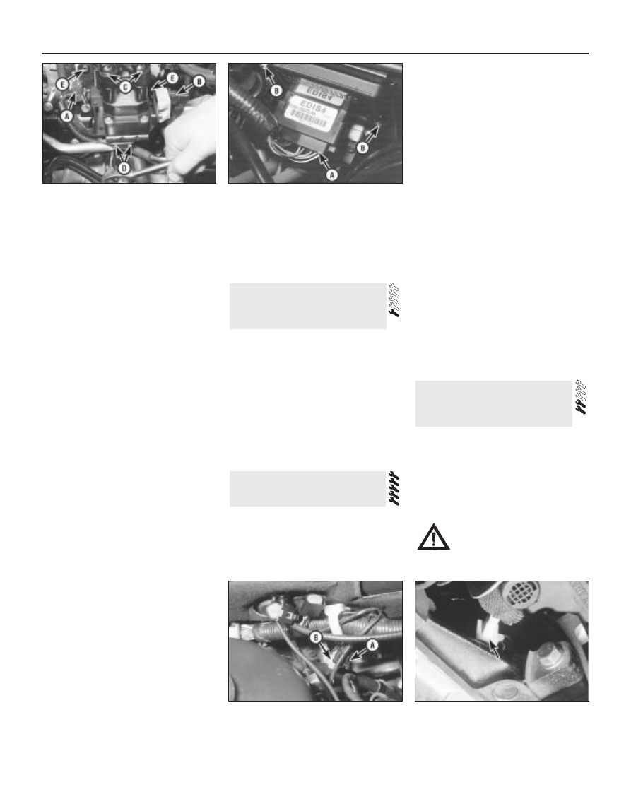
6.9  Unplug coil electrical connector (A),

suppressor connector (B), and spark

plug/HT leads (C), remove screws (D), then

undo Torx-type screws (E) to release

ignition coil assembly

7.3  Separate ignition module is fitted to

automatic transmission models only - note

electrical connector (A) and retaining

screws (B)

8.3  Service connector (A) mounted on

engine compartment bulkhead is fitted with

“plug-in bridge” (B) to set engine to use

(unleaded) petrol of 95 RON octane rating

9.4  Location of crankshaft speed/position

sensor - connector arrowed - in front of

cylinder block/crankcase

Undo the sensor’s retaining screw and
withdraw the sensor. The sensor’s bracket
cannot be unbolted from the cylinder
block/crankcase unless the transmission and
flywheel/driveplate have been removed (see
Chapter 2).
Refitting is the reverse of the removal
procedure.

General information

The charging system includes the

alternator, an internal voltage regulator, a no-
charge (or “ignition”) warning light, the
battery, and the wiring between all the
components. The charging system supplies
electrical power for the ignition system, the
lights, the radio, etc. The alternator is driven
by the auxiliary drivebelt at the front (right-
hand end) of the engine.

The purpose of the voltage regulator is to

limit the alternator’s voltage to a preset value.
This prevents power surges, circuit overloads,
etc., during peak voltage output.

The charging system doesn’t ordinarily

require periodic maintenance. However, the
drivebelt, battery and wires and connections
should be inspected at the intervals outlined
in Chapter 1.

The dashboard warning light should come

on when the ignition key is turned to positions
“II” or “III”, then should go off immediately the
engine starts. If it remains on, or if it comes on
while the engine is running, there is a
malfunction in the charging system (see
Section 11). If the light does not come on
when the ignition key is turned, and the bulb is
sound (see Chapter 12), there is a fault in the
alternator.

Precautions

Be very careful when making electrical

circuit connections to a vehicle equipped with
an alternator, and note the following:
(a) When reconnecting wires to the alternator

from the battery, be sure to note the
polarity.

(b) Before using arc-welding equipment to

repair any part of the vehicle, disconnect
the wires from the alternator and the
battery terminals.

(c) Never start the engine with a battery

charger connected.

(d) Always disconnect both battery leads

before using a battery charger.

(e) The alternator is driven by an engine

drivebelt which could cause serious injury
if your hand, hair or clothes become
entangled in it with the engine running.

(f)

Because the alternator is connected
directly to the battery, it could arc or
cause a fire if overloaded or shorted-out.

(g) Wrap a plastic bag over the alternator,

and secure it with rubber bands, before

steam-cleaning or pressure-washing the
engine.

(h) Never disconnect the alternator terminals

while the engine is running.

If a malfunction occurs in the charging
circuit, don’t automatically assume that the
alternator is causing the problem. First check
the following items:
(a) Check the tension and condition of the

auxiliary drivebelt - renew it if it is worn or
deteriorated (see Chapter 1).

(b) Ensure the alternator mounting bolts and

nuts are tight.

(c) Inspect the alternator wiring harness and

the electrical connections at the
alternator; they must be in good
condition, and tight.

(d) Check the large main fuses in the engine

compartment (see Chapter 12). If any is
blown, determine the cause, repair the
circuit and renew the fuse (the vehicle
won’t start and/or the accessories won’t
work if the fuse is blown).

(e) Start the engine and check the alternator

for abnormal noises - for example, a
shrieking or squealing sound may indicate
a badly-worn bearing or brush.

(f)

Make sure that the battery is fully-charged
- one bad cell in a battery can cause
overcharging by the alternator.

(g) Disconnect the battery leads (negative

first, then positive). Inspect the battery
posts and the lead clamps for corrosion.
Clean them thoroughly if necessary (see
Section 3 and Chapter 1). Reconnect the
lead to the negative terminal.

(h) With the ignition and all accessories

switched off, insert a test light between
the battery negative post and the
disconnected negative lead clamp:

(1) If the test light does not come on, re-

attach the clamp and proceed to the next
step.

(2) If the test light comes on, there is a short

in the electrical system of the vehicle. The
short must be repaired before the
charging system can be checked.

(3) To find the short, disconnect the

alternator wiring harness:
(a) If the light goes out, the alternator is

at fault.

(b) If the light stays on, remove each fuse

until it goes out - this will tell you
which component is short-circuited.

Using a voltmeter, check the battery
voltage with the engine off. It should be
approximately 12 volts.
Start the engine and check the battery
voltage again. Increase engine speed until the
voltmeter reading remains steady; it should
now be approximately 13.5 to 14.6 volts.
Switch on as many electrical accessories
(eg the headlights, heated rear window and

heater blower) as possible, and check that the
alternator maintains the regulated voltage at
around 13 to 14 volts. The voltage may drop
and then come back up; it may also be
necessary to increase engine speed slightly,
even if the charging system is working
properly.
If the voltage reading is greater than the
specified charging voltage, renew the voltage
regulator (see Section 13).
If the voltmeter reading is less than that
specified, the fault may be due to worn
brushes, weak brush springs, a faulty voltage
regulator, a faulty diode, a severed phase
winding, or worn or damaged slip rings. The
brushes and slip rings may be checked (see
Section 13), but if the fault persists, the
alternator should be renewed or taken to an
auto-electrician for testing and repair.

Disconnect the battery negative (earth) lead
- see Section 1.
Remove the plenum chamber (see Chap-
ter 4).
Unscrew the nuts to disconnect the wiring
from the alternator (see illustration). If
additional working clearance is required, undo
the right-hand of the three screws securing
the wiring “rail” to the rear of the inlet
manifold.
Jack up and support the front right-hand
corner of the vehicle. Remove the auxiliary
drivebelt and the engine oil filter - place a wad
of rag to soak up the spilled oil (see Chap-
ter 1). Rather than refit a used filter, you are
advised to drain the engine oil, and then to fit
a new filter and refill the engine with clean oil
on reassembly. Where an engine oil cooler is
fitted, it may prove necessary to remove this
as well, to provide the clearance necessary to
remove the alternator (see Chapter 2, Part A).
Unscrew the two bolts securing the power
steering system pipes to the right-hand side
of the front suspension subframe. With the
front wheels in the straight-ahead position,
disconnect the right-hand track rod end from
the steering knuckle (see Chapter 10).
Remove the mounting bolts and nuts (one

12 Alternator 

removal and refitting

11 Charging system - testing

10 Charging system - general

information and precautions

Engine electrical systems  5•5

5

12.3  Disconnecting alternator wiring

at the top, two at the bottom). Withdraw the
alternator from the engine, and manoeuvre it
out through the wheel arch (see illustration).
Do not drop it, it is fragile.
If you are renewing the alternator, take the
old one with you when purchasing a
replacement unit. Make sure that the new or
rebuilt unit is identical to the old alternator.
Look at the terminals - they should be the
same in number, size and location as the
terminals on the old alternator. Finally, look at
the identification markings - they will be
stamped in the housing, or printed on a tag or
plaque affixed to the housing. Make sure that
these numbers are the same on both
alternators.
Many new/rebuilt alternators do not have a
pulley installed, so you may have to switch the
pulley from the old unit to the new/rebuilt one.
When buying an alternator, ask about the
installation of pulleys - some auto-electrical
specialists will perform this service free of
charge.
Refitting is the reverse of the removal
procedure, referring where necessary to the
relevant Chapters of this manual. Tighten all
fasteners to the specified torque wrench
settings.
10 Check the charging voltage to verify
proper operation of the alternator (see Sec-
tion 11).

Note:

This procedure assumes that

replacement parts of the correct type have
been obtained. At the time of writing, no
individual alternator components were
available as separate replacement Ford parts.
An auto electrical specialist should be able to
supply parts such as brushes.

The following procedure is for the Bosch

unit fitted to the project vehicle - details may
vary for other alternator types.
Remove the alternator from the vehicle (see
Section 12) and place it on a clean
workbench.
Remove the three screws, and withdraw the
plastic end cover (see illustration).

Remove the two voltage regulator/brush
holder mounting screws.
Remove the regulator/brush holder from the
end frame (see illustration). If you are
renewing the assembly, proceed to para-
graph 8, install the new unit, reassemble the
alternator, and refit it to the engine (see
Section 12). If you are going to check the
brushes, proceed to the next paragraph.
Measure the exposed length of each brush,
and compare it to the minimum length listed in
this Chapter’s Specifications. If the length of
either brush is less than the specified
minimum, renew the assembly.
Make sure that each brush moves smoothly
in the brush holder.
Check that the slip rings - the ring of
copper on which each brush bears - are
clean. Wipe them with a solvent-moistened
cloth; if either appears scored or blackened,
take the alternator to a repair specialist for
advice.
Refit the voltage regulator/brush holder,
ensuring that the brushes bear correctly on
the slip rings, and that they compress into
their holders. Tighten the screws securely.
Install the rear cover, and tighten the
screws securely.
10 Refit the alternator (see Section 12).

General information

The sole function of the starting system is

to turn over the engine quickly enough to
allow it to start.

The starting system consists of the battery,

the starter motor, the starter solenoid, and the
wires connecting them. The solenoid is
mounted directly on the starter motor.

The solenoid/starter motor assembly is

installed on the rear upper part of the engine,
next to the transmission bellhousing.

When the ignition key is turned to position

“III”, the starter solenoid is actuated through
the starter control circuit. The starter solenoid
then connects the battery to the starter. The
battery supplies the electrical energy to the

starter motor, which does the actual work of
cranking the engine.

The starter motor on a vehicle equipped

with automatic transmission can be operated
only when the selector lever is in Park or
Neutral (“P” or “N”).

If the alarm system is armed or activated,

the starter motor cannot be operated. The
same applies with the engine immobiliser
system (where fitted).

Precautions

Always observe the following precautions

when working on the starting system:
(a) Excessive cranking of the starter motor

can overheat it, and cause serious
damage. Never operate the starter motor
for more than 15 seconds at a time
without pausing to allow it to cool for at
least two minutes. Excessive starter
operation will also risk unburned fuel
collecting in the catalytic converter’s
element, causing it to overheat when the
engine does start (see Chapter 6).

(b) The starter is connected directly to the

battery, and could arc or cause a fire if
mishandled, overloaded or shorted-out.

(c) Always detach the lead from the negative

terminal of the battery before working on
the starting system (see Section 1).

Note: Before diagnosing starter problems,
make sure that the battery is fully-charged,
and ensure that the alarm/engine immobiliser
system is not activated.
If the starter motor does not turn at all when
the switch is operated, make sure that, on
automatic transmission models, the selector
lever is in Park or Neutral (“P” or “N”).
Make sure that the battery is fully-charged,
and that all leads, both at the battery and
starter solenoid terminals, are clean and
secure.
If the starter motor spins but the engine is
not cranking, the overrunning clutch or (when
applicable) the reduction gears in the starter
motor may be slipping, in which case the

15 Starting system - testing

14 Starting system - general

information and precautions

13 Alternator brushes and

voltage regulator - renewal

5•6 Engine electrical systems

12.6  Alternator must be withdrawn

through right-hand front wheel arch

13.2  Renewing voltage regulator/brush

holder - Bosch alternator. Remove three

screws and withdraw end cover . . .

13.4  . . . then remove regulator/brush

holder assembly (secured by two screws)

starter motor must be overhauled or renewed.
(Other possibilities are that the starter motor
mounting bolts are very loose, or that teeth
are missing from the flywheel/driveplate ring
gear.)
If, when the switch is actuated, the starter
motor does not operate at all but the solenoid
clicks, then the problem lies with either the
battery, the main solenoid contacts, or the
starter motor itself (or the engine is seized).
If the solenoid plunger cannot be heard to
click when the switch is actuated, the battery
is faulty, there is a fault in the circuit, or the
solenoid itself is defective.
To check the solenoid, connect a fused
jumper lead between the battery (+) and the
ignition switch terminal (the small terminal) on
the solenoid. If the starter motor now
operates, the solenoid is OK, and the problem
is in the ignition switch, selector lever position
sensor (automatic transmission) or in the
wiring.
If the starter motor still does not operate,
remove it (see Section 16). The brushes and
commutator may be checked (see Sec-
tion 17), but if the fault persists, the motor
should be renewed, or taken to an auto-
electrician for testing and repair.
If the starter motor cranks the engine at an

abnormally-slow speed, first make sure that
the battery is charged, and that all terminal
connections are tight. If the engine is partially
seized, or has the wrong viscosity oil in it, it
will crank slowly.
Run the engine until normal operating
temperature is reached, then switch off and
disable the ignition system by unplugging the
ignition coil’s electrical connector; remove
fuse 14 to disconnect the fuel pump.
10 Connect a voltmeter positive lead to the
battery positive terminal, and connect the
negative lead to the negative terminal.
11 Crank the engine, and take the voltmeter
readings as soon as a steady figure is
indicated. Do not allow the starter motor to
turn for more than 15 seconds at a time. A
reading of 10.5 volts or more, with the starter
motor turning at normal cranking speed, is
normal. If the reading is 10.5 volts or more but
the cranking speed is slow, the solenoid
contacts are burned, the motor is faulty, or
there is a bad connection. If the reading is less
than 10.5 volts and the cranking speed is
slow, the starter motor is faulty or there is a
problem with the battery.

Disconnect the battery negative (earth) lead
- see Section 1.
Remove the air mass meter and resonator -
refer to Chapter 4.
Unscrew the upper two starter motor
mounting bolts, noting that one also secures
an engine/transmission earth lead (see
illustration)
.
Raise the front of the vehicle, and support it
securely on axle stands. 

Warning: Do not place any part of
your body under a vehicle when
it’s supported only by a jack!

Unscrew the nuts to disconnect the wiring
from the starter/solenoid terminals.
Remove the remaining starter motor
mounting bolt (see illustration). Remove the
starter.
Refitting is the reverse of the removal
procedure. Tighten the bolts to the specified
torque wrench settings.

Note:

This procedure assumes that

replacement brushes of the correct type have
been obtained - at the time of writing, no
individual starter motor components were
available as separate replacement Ford parts.
An auto electrical specialist should be able to
supply parts such as brushes.

The following procedures are for the

Lucas/Magneti Marelli unit fitted to the project
vehicle - the procedure is essentially the same
for the Bosch unit that may be found on other
models.
Remove the starter motor from the vehicle
(Section 16) (see illustration).

17 Starter motor - brush and

solenoid renewal

16 Starter motor 

removal and refitting

Engine electrical systems  5•7

5

16.3  Unscrew upper two starter motor

mounting bolts (arrowed) from above

16.6  Disconnect starter motor wiring (A),

then unscrew remaining mounting bolt (B),

and remove starter motor from beneath

vehicle

17.1  Exploded view of the Bosch DW starter

motor

1  Solenoid
2  Spring
3  Plunger
4  Engaging lever
5  Drive end housing
6  Drive pinion and 

clutch

7  Spacer
8  Ring gear and carrier
9  Output shaft and

planet gear unit

10  Circlip

11  Screw
12  End cap
13  C-clip
14  Shim
15  Commutator end 

housing

16  Brushplate
17  Yoke
18  Rubber block
19  Armature
20  Retaining plate


Content   ..  93  94  95  96   ..