Ford Mondeo (petrol engines). Manual - part 88


  Index      Ford     Ford Mondeo - service and repair manual (petrol engines)


Search            


Content   ..  86  87  88  89   ..


Ford Mondeo (petrol engines). Manual - part 88


(see illustration). Next, install the upper side
rail in the same manner.
After the three oil ring components have
been installed, check that both the upper and
lower side rails can be turned smoothly in the
ring groove.
The second compression (middle) ring is
installed next, followed by the top
compression ring - ensure their marks are
uppermost, and be careful not to confuse
them. Don’t expand either ring any more than
necessary to slide it over the top of the piston.
10 With all the rings in position, space the
ring gaps (including the elements of the oil
control ring) uniformly around the piston at
120° intervals. Repeat the procedure for the
remaining pistons and rings.

Crankshaft refitting is the first major step in
engine reassembly. It is assumed at this point
that the cylinder block/crankcase and
crankshaft have been cleaned, inspected and
repaired or reconditioned as necessary.
Position the engine upside-down.
Remove the main bearing cap bolts, and lift

out the caps. Lay the caps out in the proper
order, to ensure correct installation.
If they’re still in place, remove the old
bearing shells from the block and the main
bearing caps. Wipe the bearing recesses of
the block and caps with a clean, lint-free
cloth. They must be kept spotlessly-clean!

Main bearing running clearance
check

Clean the backs of the new main bearing
shells. Fit the shells with an oil groove in each
main bearing location in the block; note the
thrustwashers integral with the No 3 (centre)
main bearing upper shell. Fit the other shell
from each bearing set in the corresponding
main bearing cap. Make sure the tab on each
bearing shell fits into the notch in the block or
cap. Also, the oil holes in the block must line
up with the oil holes in the bearing shell (see
illustration)
.

Caution: Don’t hammer the shells
into place, and don’t nick or gouge
the bearing faces. No lubrication
should be used at this time.

Clean the bearing surfaces of the shells in

the block and the crankshaft main bearing
journals with a clean, lint-free cloth. Check or
clean the oil holes in the crankshaft, as any
dirt here can go only one way - straight
through the new bearings.
Once you’re certain the crankshaft is clean,
carefully lay it in position in the main bearings.
Trim several pieces of the appropriate-size
Plastigage (they must be slightly shorter than
the width of the main bearings), and place one
piece on each crankshaft main bearing
journal, parallel with the crankshaft centre-line
(see illustration).
Clean the bearing surfaces of the cap
shells, and install the caps in their respective
positions (don’t mix them up) with the arrows
pointing to the timing belt end of the engine.
Don’t disturb the Plastigage (see illustration).
Working on one cap at a time, from the
centre main bearing outwards (and ensuring
that each cap is tightened down squarely and
evenly onto the block), tighten the main
bearing cap bolts to the specified torque
wrench setting. Don’t rotate the crankshaft at
any time during this operation!
Remove the bolts, and carefully lift off the
main bearing caps. Keep them in order. Don’t
disturb the Plastigage or rotate the
crankshaft. If any of the main bearing caps are
difficult to remove, tap them gently from side-
to-side with a soft-faced mallet to loosen
them.
10 Compare the width of the crushed
Plastigage on each journal with the scale
printed on the Plastigage envelope to obtain
the main bearing running clearance (see
illustration)
. Check the Specifications to
make sure that the clearance is correct.
11 If the clearance is not as specified, seek
the advice of a Ford dealer or similar engine
reconditioning specialist - if the crankshaft
journals are in good condition (see Sec-
tion 13), it may be possible simply to renew
the shells to achieve the correct clearance. If
this is not possible, the crankshaft must be
reground by a specialist who can supply the
necessary undersized shells. First though,

17 Crankshaft 

refitting and main bearing
running clearance check

2B•20 Engine removal and general engine overhaul procedures

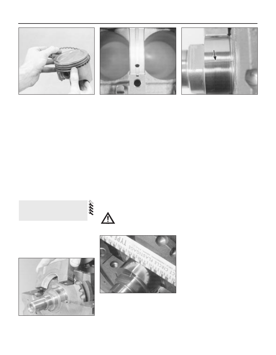
16.7B  DO NOT use a piston ring

installation tool when installing the oil ring

side rails

17.4  Tab on each bearing shell must

engage with notch in block or cap, and oil

holes in upper shells must align with block

oilways

17.6  Lay the Plastigage strips (arrowed) on

the main bearing journals, parallel to the

crankshaft centre-line

17.7  Refit the main bearing caps and

tighten the bolts as specified

17.10  Compare the width of the crushed

Plastigage to the scale on the envelope to

determine the main bearing oil clearance

(always take the measurement at the

widest point of the Plastigage). Be sure to
use the correct scale; Imperial and metric

scales are included

make sure that no dirt or oil was between the
bearing shells and the caps or block when the
clearance was measured. If the Plastigage is
noticeably wider at one end than the other,
the journal may be tapered (see Section 13).
12 Carefully scrape all traces of the
Plastigage material off the main bearing
journals and the bearing surfaces. Be very
careful not to scratch the bearing - use your
fingernail or the edge of a credit card.

Final refitting

13 Carefully lift the crankshaft out of the
engine. Clean the bearing surfaces of the
shells in the block, then apply a thin, uniform
layer of clean molybdenum disulphide-based
grease, engine assembly lubricant, or clean
engine oil to each surface (see illustration).
Coat the thrustwasher surfaces as well.
14 Lubricate the crankshaft oil seal journals
with molybdenum disulphide-based grease,
engine assembly lubricant, or clean engine oil.
15 Make sure the crankshaft journals are
clean, then lay the crankshaft back in place in
the block (see illustration). Clean the bearing
surfaces of the shells in the caps, then
lubricate them. Install the caps in their
respective positions, with the arrows pointing
to the timing belt end of the engine.
16 Working on one cap at a time, from the
centre main bearing outwards (and ensuring
that each cap is tightened down squarely and
evenly onto the block), tighten the main

bearing cap bolts to the specified torque
wrench setting.
17 Rotate the crankshaft a number of times
by hand, to check for any obvious binding.
18 Check the crankshaft endfloat (see
Section 10). It should be correct if the
crankshaft thrust faces aren’t worn or
damaged, and if the No 3 (centre) main
bearing’s upper shell has been renewed.
19 Refit the crankshaft left-hand oil seal
carrier, and install a new seal (see Part A of
this Chapter, Section 20).

Before refitting the piston/connecting rod
assemblies, the cylinder bores must be
perfectly clean, the top edge of each cylinder
must be chamfered, and the crankshaft must
be in place.
Remove the big-end bearing cap from No 1
cylinder connecting rod (refer to the marks
noted or made on removal). Remove the
original bearing shells, and wipe the bearing
recesses of the connecting rod and cap with a
clean, lint-free cloth. They must be kept
spotlessly-clean!

Big-end bearing running
clearance check

Clean the back of the new upper bearing
shell, fit it to the connecting rod, then fit the
other shell of the bearing set to the big-end
bearing cap. Make sure the tab on each shell
fits into the notch in the rod or cap recess
(see illustration).

Caution: Don’t hammer the shells
into place, and don’t nick or
gouge the bearing face. Don’t
lubricate the bearing at this time.

It’s critically important that all mating
surfaces of the bearing components are
perfectly clean and oil-free when they’re
assembled.
Position the piston ring gaps as described
in Section 16, lubricate the piston and rings
with clean engine oil, and attach a piston ring
compressor to the piston. Leave the skirt
protruding about a quarter-inch, to guide the
piston into the cylinder bore. The rings must
be compressed until they’re flush with the
piston.
Rotate the crankshaft until No 1 crankpin
(big-end) journal is at BDC (Bottom Dead
Centre), and apply a coat of engine oil to the
cylinder walls.
Arrange the No 1 piston/connecting rod
assembly so that the arrow on the piston
crown points to the timing belt end of the
engine. The cylinder number (counting from
the timing belt end of the engine) is etched
into the flat-machined surface of the
connecting rod and its cap, and must be
visible from the front (exhaust side) of the
engine (see illustrations 9.5A and 9.5B).
Gently insert the assembly into the No 1
cylinder bore, and rest the bottom edge of the
ring compressor on the engine block.
Tap the top edge of the ring compressor to
make sure it’s contacting the block around its
entire circumference.
Gently tap on the top of the piston with the
end of a wooden hammer handle (see
illustration)
, while guiding the connecting

18 Piston/connecting rod

assemblies -
refitting and big-end bearing
running clearance check

Engine removal and general engine overhaul procedures  2B•21

2B

18.3  Tab on each big-end bearing shell

must engage with notch in connecting rod

or cap

18.9  The piston can be driven gently into

the cylinder bore with the end of a wooden

or plastic hammer handle

18.11  The connecting rod and big-end

bearing cap of each assembly must share

the same etched cylinder number, visible
from the same (front/exhaust) side of the

engine

17.13  Ensure bearing shells are absolutely

clean, lubricate liberally . . .

17.15  . . . and refit the crankshaft

rod’s big-end onto the crankpin. The piston
rings may try to pop out of the ring
compressor just before entering the cylinder
bore, so keep some pressure on the ring
compressor. Work slowly, and if any
resistance is felt as the piston enters the
cylinder, stop immediately. Find out what’s
binding, and fix it before proceeding. Do not,
for any reason, force the piston into the
cylinder - you might break a ring and/or the
piston.
10 To check the big-end bearing running
clearance, cut a piece of the appropriate-size
Plastigage slightly shorter than the width of
the connecting rod bearing, and lay it in place
on the No 1 crankpin (big-end) journal, parallel
with the crankshaft centre-line (see illus-
tration 17.6).
11 Clean the connecting rod-to-cap mating
surfaces, and refit the big-end bearing cap.
Make sure the etched number on the cap is
on the same side as that on the rod (see
illustration)
. Tighten the cap bolts evenly -
first use a torque wrench to tighten the bolts
to the specified (first stage) torque setting,
then use an ordinary socket extension bar
and an angle gauge to tighten the bolts
further through the specified (second stage)
angle. Use a thin-wall socket, to avoid
erroneous torque readings that can result if
the socket is wedged between the cap and
nut. If the socket tends to wedge itself
between the nut and the cap, lift up on it
slightly until it no longer contacts the cap.
Don’t rotate the crankshaft at any time during
this operation!
12 Unscrew the bolts and detach the cap,
being very careful not to disturb the
Plastigage.
13 Compare the width of the crushed
Plastigage to the scale printed on the
Plastigage envelope, to obtain the running
clearance (see illustration 17.10). Compare it
to the Specifications, to make sure the
clearance is correct.
14 If the clearance is not as specified, seek
the advice of a Ford dealer or similar engine
reconditioning specialist - if the crankshaft
journals are in good condition (see Sec-
tion 13), it may be possible simply to renew
the shells to achieve the correct clearance. If
this is not possible, the crankshaft must be

reground by a specialist, who can also supply
the necessary undersized shells. First though,
make sure that no dirt or oil was trapped
between the bearing shells and the
connecting rod or cap when the clearance
was measured. Also, recheck the crankpin
diameter. If the Plastigage was wider at one
end than the other, the crankpin journal may
be tapered (see Section 13).
15 Carefully scrape all traces of the
Plastigage material off the journal and the
bearing surface. Be very careful not to scratch
the bearing - use your fingernail or the edge of
a credit card.

Final piston/connecting rod
refitting

16 Make sure the bearing surfaces are
perfectly clean, then apply a uniform layer of
clean molybdenum disulphide-based grease,
engine assembly lubricant, or clean engine oil,
to both of them. You’ll have to push the piston
into the cylinder to expose the bearing surface
of the shell in the connecting rod.
17 Slide the connecting rod back into place
on the crankpin (big-end) journal, refit the big-
end bearing cap, and then tighten the bolts in
two stages, as described above.
18 Repeat the entire procedure for the
remaining piston/connecting rod assemblies.
19 The important points to remember are:
(a) Keep the backs of the bearing shells and

the recesses of the connecting rods and
caps perfectly clean when assembling
them.

(b) Make sure you have the correct

piston/rod assembly for each cylinder -
use the etched cylinder numbers to
identify the front-facing side of both the
rod and its cap.

(c) The arrow on the piston crown must face

the timing belt end of the engine.

(d) Lubricate the cylinder bores with clean

engine oil.

(e) Lubricate the bearing surfaces when

refitting the big-end bearing caps after the
running clearance has been checked.

20 After all the piston/connecting rod
assemblies have been properly installed,
rotate the crankshaft a number of times by
hand, to check for any obvious binding.

With the engine refitted in the vehicle,
double-check the engine oil and coolant
levels. Make a final check that everything has
been reconnected, and that there are no tools
or rags left in the engine compartment.
With the spark plugs removed and the
ignition system disabled by unplugging the
ignition coil’s electrical connector, remove
fuse 14 to disconnect the fuel pump. Turn the
engine on the starter until the oil pressure
warning light goes out.
Refit the spark plugs, and connect all the
spark plug (HT) leads (Chapter 1). Reconnect
the ignition coil wiring, refit the fuel pump fuse,
then switch on the ignition and listen for the fuel
pump; it will run for a little longer than usual,
due to the lack of pressure in the system.
Start the engine, noting that this also may
take a little longer than usual, due to the fuel
system components being empty.
While the engine is idling, check for fuel,
coolant and oil leaks. Don’t be alarmed if
there are some odd smells and smoke from
parts getting hot and burning off oil deposits.
If the hydraulic tappets have been disturbed,
some valve gear noise may be heard at first;
this should disappear as the oil circulates fully
around the engine, and normal pressure is
restored in the tappets.
Keep the engine idling until hot water is felt
circulating through the top hose, check that it
idles reasonably smoothly and at the usual
speed, then switch it off.
After a few minutes, recheck the oil and
coolant levels, and top-up as necessary
(Chapter 1).
If they were tightened as described, there is
no need to re-tighten the cylinder head bolts
once the engine has first run after reassembly
- in fact, Ford state that the bolts must not be
re-tightened.
If new components such as pistons, rings
or crankshaft bearings have been fitted, the
engine must be run-in for the first 500 miles
(800 km). Do not operate the engine at full-
throttle, or allow it to labour in any gear during
this period. It is recommended that the oil and
filter be changed at the end of this period.

19 Engine 

initial start-up after overhaul

2B•22 Engine removal and general engine overhaul procedures

Chapter 3
Cooling, heating, and air conditioning systems

Air conditioning system - general information 
and precautions  . . . . . . . . . . . . . . . . . . . . . . . . . . . . . . . . . . . . . . . . 11
Air conditioning system components - removal and refitting  . . . . . . 12
Antifreeze - general information  . . . . . . . . . . . . . . . . . . . . . . . . . . . .

2

Auxiliary drivebelt check and renewal  . . . . . . . . . . . . .

See Chapter 1

Coolant level check  . . . . . . . . . . . . . . . . . . . . . . . . . . .

See Chapter 1

Coolant renewal  . . . . . . . . . . . . . . . . . . . . . . . . . . . . . .

See Chapter 1

Cooling system checks (coolant leaks, 

hose condition) . . . . . . . . . . . . . . . . . . . . . . . . . . . . .

See Chapter 1

Cooling system electrical switches and sensors - 

testing, removal and refitting . . . . . . . . . . . . . . . . . . . . . . . . . . . . .

6

Cooling system hoses - disconnection and renewal  . . . . . . . . . . . .

3

Cooling system servicing (draining, flushing 

and refilling)  . . . . . . . . . . . . . . . . . . . . . . . . . . . . . . .

See Chapter 1

General information . . . . . . . . . . . . . . . . . . . . . . . . . . . . . . . . . . . . . .

1

Heater/air conditioning controls - removal and refitting  . . . . . . . . . . 10
Heater/ventilation components - removal and refitting . . . . . . . . . . .

9

Pollen filter renewal  . . . . . . . . . . . . . . . . . . . . . . . . . . .

See Chapter 1

Radiator and expansion tank - removal, inspection 
and refitting  . . . . . . . . . . . . . . . . . . . . . . . . . . . . . . . . . . . . . . . . . . . .

7

Radiator electric cooling fan(s) - testing, removal and refitting . . . . .

5

Thermostat - removal, testing and refitting  . . . . . . . . . . . . . . . . . . . .

4

Water pump - check, removal and refitting . . . . . . . . . . . . . . . . . . . .

8

Coolant

Mixture type  . . . . . . . . . . . . . . . . . . . . . . . . . . . . . . . . . . . . . . . . . . . . . .

See Chapter 1

Cooling system capacity . . . . . . . . . . . . . . . . . . . . . . . . . . . . . . . . . . . . .

See Chapter 1

System pressure

Pressure test  . . . . . . . . . . . . . . . . . . . . . . . . . . . . . . . . . . . . . . . . . . . . . .

1.2 bars - should hold this pressure for at least 10 seconds

Expansion tank filler cap

Pressure rating  . . . . . . . . . . . . . . . . . . . . . . . . . . . . . . . . . . . . . . . . . . . .

1.2 bars approximately - see cap for actual value

Thermostat

Starts to open  . . . . . . . . . . . . . . . . . . . . . . . . . . . . . . . . . . . . . . . . . . . . .

88°C

Radiator electric cooling fan

Switches on at:

Single-speed fans, two-speed fans - first stage  . . . . . . . . . . . . . . . . .

100°C

Two-speed fans - second stage  . . . . . . . . . . . . . . . . . . . . . . . . . . . . .

103°C

Switches off at:

Single-speed fans, two-speed fans - first stage  . . . . . . . . . . . . . . . . .

93°C

Two-speed fans - second stage  . . . . . . . . . . . . . . . . . . . . . . . . . . . . .

100°C

Coolant temperature sensor

Resistance:

At -40°C . . . . . . . . . . . . . . . . . . . . . . . . . . . . . . . . . . . . . . . . . . . . . . . .

860.0 to 900.0 kilohms

At 20°C  . . . . . . . . . . . . . . . . . . . . . . . . . . . . . . . . . . . . . . . . . . . . . . . .

35.0 to 40.0 kilohms

At 100°C  . . . . . . . . . . . . . . . . . . . . . . . . . . . . . . . . . . . . . . . . . . . . . . .

1.9 to 2.5 kilohms

At 120°C  . . . . . . . . . . . . . . . . . . . . . . . . . . . . . . . . . . . . . . . . . . . . . . .

1.0 to 1.3 kilohms

Air conditioning system

Refrigerant . . . . . . . . . . . . . . . . . . . . . . . . . . . . . . . . . . . . . . . . . . . . . . . .

R134a

3•1

Easy, suitable for
novice with little
experience

Fairly easy, suitable
for beginner with
some experience

Fairly difficult, suitable
for competent DIY
mechanic

Difficult, suitable for
experienced  DIY
mechanic

Very difficult,
suitable for expert DIY
or  professional

Degrees of difficulty

Specifications

Contents

3


Content   ..  86  87  88  89   ..