Ford Mondeo (petrol engines). Manual - part 55
the specified mileage (or time) since the last
service has been reached.
4 To reset the service interval system and
turn off the light, a switch inside the glovebox
must be depressed for a minimum of 4
seconds with the ignition switched on. This
should be carried out by a Ford dealer if the
vehicle is still in the warranty period.
Component renewal
5 The following paragraphs describe brief
removal procedures for the auxiliary warning
system components. Disconnect the battery
negative (earth) lead before commencing
work (refer to Chapter 5, Section 1). Refitting
procedures are a reversal of removal.
Display warning bulb
6 Remove the control assembly.
7 Prise off the cover, and pull out the relevant
bulb and bulbholder.
Low air temperature warning sender
unit
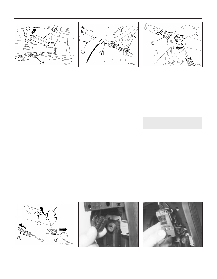
8 Remove the front bumper.
9 Unclip the sender unit and disconnect the
multi-plug (see illustration).
Engine oil level sensor
10 Apply the handbrake, jack up the front of
the vehicle and support it on axle stands.
11 Place a container beneath the oil level
sensor, to catch any spilt oil.
12 Unscrew the screws and remove the
cover from the sensor.
13 Disconnect the multi-plug.
14 Unscrew and remove the sensor, and
remove the seal (see illustration).
Door ajar sensor
15 Remove the door lock as described in
Chapter 11, Section 14.
16 Unclip the sensor and disconnect the
multi-plug.
Low coolant warning switch
17 Refer to Chapter 3, Section 6.
Low washer fluid switch
18 Disconnect the multi-plug from the
washer fluid reservoir.
19 Drain or syphon out the fluid from the
reservoir.
20 Using a screwdriver, lever out the switch
from the reservoir (see illustration).
Service indicator reset switch
21 Remove the glove compartment lid as
described in Chapter 11, Section 32.
22 Carefully lever out the switch using a
small screwdriver.
23 Remove the rear cover and disconnect
the wiring (see illustration).
Control assembly
24 Remove the instrument panel surround,
referring to Section 10.
25 Unscrew the mounting screws,
disconnect the multi-plugs and remove the
assembly.
Bulb failure module
26 Remove the lower facia panel from under
the steering wheel.
27 Unclip the bulb failure module and
disconnect the multi-plug.
Note: From November 1993, for added
security, a complex Bosch immobiliser system
was fitted to some models. For further details,
refer to your Ford dealer.
1 All UK models are fitted with an anti-theft
alarm system, incorporating movement
sensors and an ignition immobiliser. The
system is activated when the vehicle is
locked.
2 The system includes a start inhibitor circuit,
which makes it impossible to start the engine
with the system armed.
3 The movement sensors consist of two
ultrasonic units, located in the “B” pillars,
incorporating transmitters and receivers (see
illustrations). The receivers check that the
echo frequency matches the original
frequency. If there is any significant
difference, the system triggers the alarm.
20 Anti-theft alarm system - general
information
12•18 Body electrical system
19.9 Low air temperature sender unit
removal
1 Clip 2 Sender unit 3 Multi-plug
19.14 Engine oil level sensor removal
1 Cover 2 Multi-plug 3 Sensor 4 Seal
19.20 Removing the low washer fluid
switch
19.23 Service indicator switch removal
1 Lever out the switch 2 Cover 3 Wiring
20.3A Disconnecting a movement sensor
multi-plug
20.3B Removing a movement sensor