Ford Mondeo (petrol engines). Manual - part 33
and remove the clevis pin securing the servo
unit pushrod to the pedal cross-link arm.
7 On left-hand drive models, unscrew the nut
securing the pedal trunnion to the servo unit
pushrod inside the passenger compartment.
The nut is located near the top of the pedal,
and is accessible through an access hole. For
improved access, remove the lower facia
panel first.
8 Withdraw the servo unit from the bulkhead,
and remove it from the engine compartment.
On left-hand drive models, take care not to
damage the bulkhead rubber grommet as the
pushrod passes through it.
9 Note that the servo unit cannot be
dismantled for repair or overhaul and, if faulty,
must be renewed.
Refitting
10 Refitting is a reversal of the removal
procedure. Refer to Section 11 for details of
refitting the master cylinder.
Removal
1 Depress the brake pedal four or five times,
to dissipate any remaining vacuum from the
servo unit.
2 Disconnect the vacuum hose adaptor at the
servo unit, by pulling it free from the rubber
grommet (see illustration). If it is reluctant to
move, prise it free, using a screwdriver with its
blade inserted under the flange.
3 Detach the vacuum hose from the inlet
manifold connection, pressing in the collar to
disengage the tabs, then withdrawing the
collar slowly.
4 If the hose or the fixings are damaged or in
poor condition, they must be renewed.
Testing
5 Examine the non-return valve for damage
and signs of deterioration, and renew it if
necessary. The valve may be tested by
blowing through its connecting hoses in both
directions. It should only be possible to blow
from the servo end towards the inlet manifold.
Refitting
6 Refitting is a reversal of the removal
procedure. If fitting a new non-return valve,
ensure that it is fitted the correct way round.
Removal
1 On non-ABS models, the two pressure-
control relief valves (sometimes referred to as
pressure-conscious reducing valves) are
located on the master cylinder outlets to the
rear brake line circuits.
2 Unscrew and remove the fluid reservoir filler
cap, and draw off the fluid - see Section 11.
3 Position some rags beneath the master
cylinder, to catch any spilled fluid.
4 Clean around the valve to be removed.
Hold the PCR valve stationary with one
spanner, and unscrew the hydraulic pipe
union nut with another spanner. Pull out the
pipe, and bend it slightly away from the valve.
5 Unscrew the PCR valve from the master
cylinder.
6 Note that the primary and secondary PCR
valves have different thread diameters, to
prevent incorrect fitment. The primary valve
has a 12 mm diameter thread, and the
secondary valve has a 10 mm diameter thread
(see illustration).
Refitting
7 Refitting is a reversal of the removal
procedure. On completion, bleed the
hydraulic system as described in Section 15.
Removal
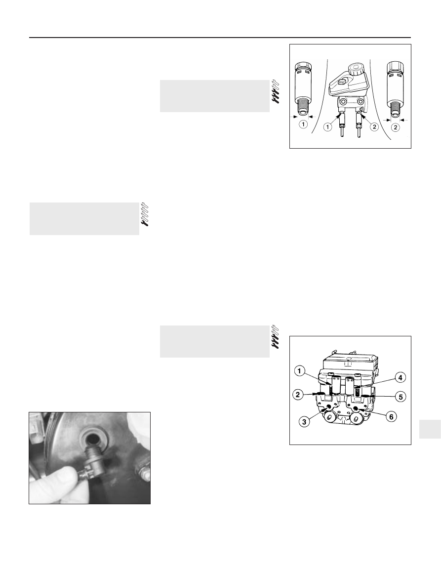
1 On ABS models, the pressure-control relief
valves are located on the ABS hydraulic unit
(see illustration).
2 Disconnect the battery negative (earth) lead
(Chapter 5, Section 1).
3 Remove the air cleaner assembly as
described in Chapter 4.
4 Remove the engine air inlet duct and air
plenum chamber.
5 Disconnect the low fluid level warning
multi-plug from the brake fluid reservoir.
6 Unscrew and remove the brake fluid
reservoir filler cap, and completely seal the
top of the reservoir using cling film or
adhesive tape. This will reduce loss of fluid
when the PCR valve is removed.
7 Unscrew the master cylinder mounting
nuts, and carefully withdraw the cylinder from
the servo unit, leaving the brake pipes still
connected to it. Move the master cylinder
over to the left-hand side of the engine
compartment, to rest against the left-hand
suspension turret. (Throughout this manual,
left- and right-hand are as seen from the
driver’s seat.)
8 Unscrew the servo unit mounting nuts, and
move the unit to one side.
9 Position some rags beneath the ABS unit,
to catch spilled fluid.
10 Clean around the valve to be removed.
Hold the PCR valve stationary with one
spanner, and unscrew the hydraulic pipe
union nut with another spanner. Pull out the
pipe, and bend it slightly away from the valve.
11 Unscrew the PCR valve from the ABS
unit.
Refitting
12 Refitting is a reversal of the removal
procedure. On completion, bleed the
hydraulic system as described in Section 15.
19 Pressure-control relief valve
(ABS models) -
removal and refitting
18 Pressure-control relief valve
(non-ABS models) -
removal and refitting
17 Vacuum servo unit vacuum
hose and non-return valve -
removal, testing and refitting
Braking system 9•13
9
17.2 Removing the plastic adaptor from
the servo unit
18.6 Pressure-control relief valve
locations
1 Primary PCR valve (12 mm)
2 Secondary PCR valve (10 mm)
19.1 Pressure-control relief valve locations
on the ABS hydraulic unit
1 PCR valve, rear right brake circuit
2 Outlet, front left brake circuit
3 Inlet, from brake master cylinder secondary
circuit
4 PCR valve, rear left brake circuit
5 Outlet, front right brake circuit
6 Inlet, from brake master cylinder primary
circuit