Ford Mondeo (petrol engines). Manual - part 22


  Index      Ford     Ford Mondeo - service and repair manual (petrol engines)


Search            


Content   ..  20  21  22  23   ..


Ford Mondeo (petrol engines). Manual - part 22


make sure that no dirt or oil was between the
bearing shells and the caps or block when the
clearance was measured. If the Plastigage is
noticeably wider at one end than the other,
the journal may be tapered (see Section 13).
12 Carefully scrape all traces of the
Plastigage material off the main bearing
journals and the bearing surfaces. Be very
careful not to scratch the bearing - use your
fingernail or the edge of a credit card.

Final refitting

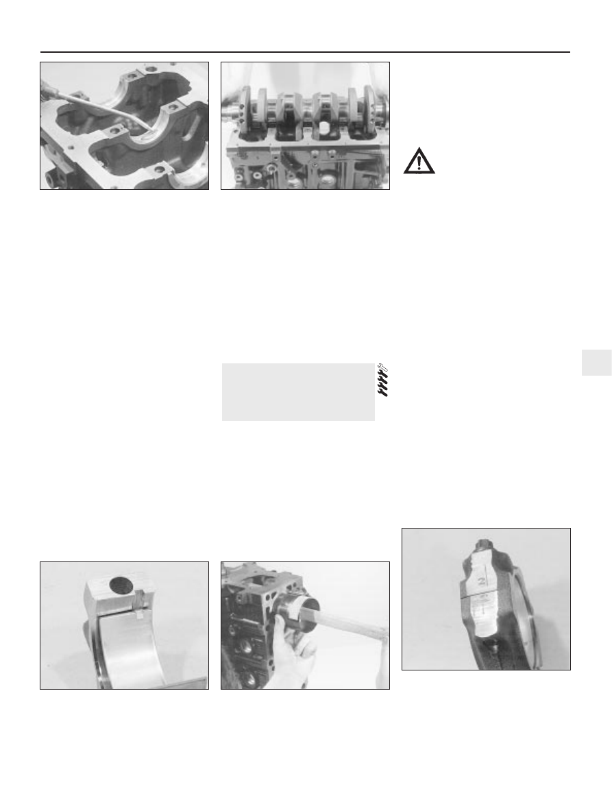
13 Carefully lift the crankshaft out of the
engine. Clean the bearing surfaces of the
shells in the block, then apply a thin, uniform
layer of clean molybdenum disulphide-based
grease, engine assembly lubricant, or clean
engine oil to each surface (see illustration).
Coat the thrustwasher surfaces as well.
14 Lubricate the crankshaft oil seal journals
with molybdenum disulphide-based grease,
engine assembly lubricant, or clean engine oil.
15 Make sure the crankshaft journals are
clean, then lay the crankshaft back in place in
the block (see illustration). Clean the bearing
surfaces of the shells in the caps, then
lubricate them. Install the caps in their
respective positions, with the arrows pointing
to the timing belt end of the engine.
16 Working on one cap at a time, from the
centre main bearing outwards (and ensuring
that each cap is tightened down squarely and
evenly onto the block), tighten the main

bearing cap bolts to the specified torque
wrench setting.
17 Rotate the crankshaft a number of times
by hand, to check for any obvious binding.
18 Check the crankshaft endfloat (see
Section 10). It should be correct if the
crankshaft thrust faces aren’t worn or
damaged, and if the No 3 (centre) main
bearing’s upper shell has been renewed.
19 Refit the crankshaft left-hand oil seal
carrier, and install a new seal (see Part A of
this Chapter, Section 20).

Before refitting the piston/connecting rod
assemblies, the cylinder bores must be
perfectly clean, the top edge of each cylinder
must be chamfered, and the crankshaft must
be in place.
Remove the big-end bearing cap from No 1
cylinder connecting rod (refer to the marks
noted or made on removal). Remove the
original bearing shells, and wipe the bearing
recesses of the connecting rod and cap with a
clean, lint-free cloth. They must be kept
spotlessly-clean!

Big-end bearing running
clearance check

Clean the back of the new upper bearing
shell, fit it to the connecting rod, then fit the
other shell of the bearing set to the big-end
bearing cap. Make sure the tab on each shell
fits into the notch in the rod or cap recess
(see illustration).

Caution: Don’t hammer the shells
into place, and don’t nick or
gouge the bearing face. Don’t
lubricate the bearing at this time.

It’s critically important that all mating
surfaces of the bearing components are
perfectly clean and oil-free when they’re
assembled.
Position the piston ring gaps as described
in Section 16, lubricate the piston and rings
with clean engine oil, and attach a piston ring
compressor to the piston. Leave the skirt
protruding about a quarter-inch, to guide the
piston into the cylinder bore. The rings must
be compressed until they’re flush with the
piston.
Rotate the crankshaft until No 1 crankpin
(big-end) journal is at BDC (Bottom Dead
Centre), and apply a coat of engine oil to the
cylinder walls.
Arrange the No 1 piston/connecting rod
assembly so that the arrow on the piston
crown points to the timing belt end of the
engine. The cylinder number (counting from
the timing belt end of the engine) is etched
into the flat-machined surface of the
connecting rod and its cap, and must be
visible from the front (exhaust side) of the
engine (see illustrations 9.5A and 9.5B).
Gently insert the assembly into the No 1
cylinder bore, and rest the bottom edge of the
ring compressor on the engine block.
Tap the top edge of the ring compressor to
make sure it’s contacting the block around its
entire circumference.
Gently tap on the top of the piston with the
end of a wooden hammer handle (see
illustration)
, while guiding the connecting

18 Piston/connecting rod

assemblies -
refitting and big-end bearing
running clearance check

Engine removal and general engine overhaul procedures  2B•21

2B

18.3  Tab on each big-end bearing shell

must engage with notch in connecting rod

or cap

18.9  The piston can be driven gently into

the cylinder bore with the end of a wooden

or plastic hammer handle

18.11  The connecting rod and big-end

bearing cap of each assembly must share

the same etched cylinder number, visible
from the same (front/exhaust) side of the

engine

17.13  Ensure bearing shells are absolutely

clean, lubricate liberally . . .

17.15  . . . and refit the crankshaft

rod’s big-end onto the crankpin. The piston
rings may try to pop out of the ring
compressor just before entering the cylinder
bore, so keep some pressure on the ring
compressor. Work slowly, and if any
resistance is felt as the piston enters the
cylinder, stop immediately. Find out what’s
binding, and fix it before proceeding. Do not,
for any reason, force the piston into the
cylinder - you might break a ring and/or the
piston.
10 To check the big-end bearing running
clearance, cut a piece of the appropriate-size
Plastigage slightly shorter than the width of
the connecting rod bearing, and lay it in place
on the No 1 crankpin (big-end) journal, parallel
with the crankshaft centre-line (see illus-
tration 17.6).
11 Clean the connecting rod-to-cap mating
surfaces, and refit the big-end bearing cap.
Make sure the etched number on the cap is
on the same side as that on the rod (see
illustration)
. Tighten the cap bolts evenly -
first use a torque wrench to tighten the bolts
to the specified (first stage) torque setting,
then use an ordinary socket extension bar
and an angle gauge to tighten the bolts
further through the specified (second stage)
angle. Use a thin-wall socket, to avoid
erroneous torque readings that can result if
the socket is wedged between the cap and
nut. If the socket tends to wedge itself
between the nut and the cap, lift up on it
slightly until it no longer contacts the cap.
Don’t rotate the crankshaft at any time during
this operation!
12 Unscrew the bolts and detach the cap,
being very careful not to disturb the
Plastigage.
13 Compare the width of the crushed
Plastigage to the scale printed on the
Plastigage envelope, to obtain the running
clearance (see illustration 17.10). Compare it
to the Specifications, to make sure the
clearance is correct.
14 If the clearance is not as specified, seek
the advice of a Ford dealer or similar engine
reconditioning specialist - if the crankshaft
journals are in good condition (see Sec-
tion 13), it may be possible simply to renew
the shells to achieve the correct clearance. If
this is not possible, the crankshaft must be

reground by a specialist, who can also supply
the necessary undersized shells. First though,
make sure that no dirt or oil was trapped
between the bearing shells and the
connecting rod or cap when the clearance
was measured. Also, recheck the crankpin
diameter. If the Plastigage was wider at one
end than the other, the crankpin journal may
be tapered (see Section 13).
15 Carefully scrape all traces of the
Plastigage material off the journal and the
bearing surface. Be very careful not to scratch
the bearing - use your fingernail or the edge of
a credit card.

Final piston/connecting rod
refitting

16 Make sure the bearing surfaces are
perfectly clean, then apply a uniform layer of
clean molybdenum disulphide-based grease,
engine assembly lubricant, or clean engine oil,
to both of them. You’ll have to push the piston
into the cylinder to expose the bearing surface
of the shell in the connecting rod.
17 Slide the connecting rod back into place
on the crankpin (big-end) journal, refit the big-
end bearing cap, and then tighten the bolts in
two stages, as described above.
18 Repeat the entire procedure for the
remaining piston/connecting rod assemblies.
19 The important points to remember are:
(a) Keep the backs of the bearing shells and

the recesses of the connecting rods and
caps perfectly clean when assembling
them.

(b) Make sure you have the correct

piston/rod assembly for each cylinder -
use the etched cylinder numbers to
identify the front-facing side of both the
rod and its cap.

(c) The arrow on the piston crown must face

the timing belt end of the engine.

(d) Lubricate the cylinder bores with clean

engine oil.

(e) Lubricate the bearing surfaces when

refitting the big-end bearing caps after the
running clearance has been checked.

20 After all the piston/connecting rod
assemblies have been properly installed,
rotate the crankshaft a number of times by
hand, to check for any obvious binding.

With the engine refitted in the vehicle,
double-check the engine oil and coolant
levels. Make a final check that everything has
been reconnected, and that there are no tools
or rags left in the engine compartment.
With the spark plugs removed and the
ignition system disabled by unplugging the
ignition coil’s electrical connector, remove
fuse 14 to disconnect the fuel pump. Turn the
engine on the starter until the oil pressure
warning light goes out.
Refit the spark plugs, and connect all the
spark plug (HT) leads (Chapter 1). Reconnect
the ignition coil wiring, refit the fuel pump fuse,
then switch on the ignition and listen for the fuel
pump; it will run for a little longer than usual,
due to the lack of pressure in the system.
Start the engine, noting that this also may
take a little longer than usual, due to the fuel
system components being empty.
While the engine is idling, check for fuel,
coolant and oil leaks. Don’t be alarmed if
there are some odd smells and smoke from
parts getting hot and burning off oil deposits.
If the hydraulic tappets have been disturbed,
some valve gear noise may be heard at first;
this should disappear as the oil circulates fully
around the engine, and normal pressure is
restored in the tappets.
Keep the engine idling until hot water is felt
circulating through the top hose, check that it
idles reasonably smoothly and at the usual
speed, then switch it off.
After a few minutes, recheck the oil and
coolant levels, and top-up as necessary
(Chapter 1).
If they were tightened as described, there is
no need to re-tighten the cylinder head bolts
once the engine has first run after reassembly
- in fact, Ford state that the bolts must not be
re-tightened.
If new components such as pistons, rings
or crankshaft bearings have been fitted, the
engine must be run-in for the first 500 miles
(800 km). Do not operate the engine at full-
throttle, or allow it to labour in any gear during
this period. It is recommended that the oil and
filter be changed at the end of this period.

19 Engine 

initial start-up after overhaul

2B•22 Engine removal and general engine overhaul procedures

Chapter 3
Cooling, heating, and air conditioning systems

Air conditioning system - general information 
and precautions  . . . . . . . . . . . . . . . . . . . . . . . . . . . . . . . . . . . . . . . . 11
Air conditioning system components - removal and refitting  . . . . . . 12
Antifreeze - general information  . . . . . . . . . . . . . . . . . . . . . . . . . . . .

2

Auxiliary drivebelt check and renewal  . . . . . . . . . . . . .

See Chapter 1

Coolant level check  . . . . . . . . . . . . . . . . . . . . . . . . . . .

See Chapter 1

Coolant renewal  . . . . . . . . . . . . . . . . . . . . . . . . . . . . . .

See Chapter 1

Cooling system checks (coolant leaks, 

hose condition) . . . . . . . . . . . . . . . . . . . . . . . . . . . . .

See Chapter 1

Cooling system electrical switches and sensors - 

testing, removal and refitting . . . . . . . . . . . . . . . . . . . . . . . . . . . . .

6

Cooling system hoses - disconnection and renewal  . . . . . . . . . . . .

3

Cooling system servicing (draining, flushing 

and refilling)  . . . . . . . . . . . . . . . . . . . . . . . . . . . . . . .

See Chapter 1

General information . . . . . . . . . . . . . . . . . . . . . . . . . . . . . . . . . . . . . .

1

Heater/air conditioning controls - removal and refitting  . . . . . . . . . . 10
Heater/ventilation components - removal and refitting . . . . . . . . . . .

9

Pollen filter renewal  . . . . . . . . . . . . . . . . . . . . . . . . . . .

See Chapter 1

Radiator and expansion tank - removal, inspection 
and refitting  . . . . . . . . . . . . . . . . . . . . . . . . . . . . . . . . . . . . . . . . . . . .

7

Radiator electric cooling fan(s) - testing, removal and refitting . . . . .

5

Thermostat - removal, testing and refitting  . . . . . . . . . . . . . . . . . . . .

4

Water pump - check, removal and refitting . . . . . . . . . . . . . . . . . . . .

8

Coolant

Mixture type  . . . . . . . . . . . . . . . . . . . . . . . . . . . . . . . . . . . . . . . . . . . . . .

See Chapter 1

Cooling system capacity . . . . . . . . . . . . . . . . . . . . . . . . . . . . . . . . . . . . .

See Chapter 1

System pressure

Pressure test  . . . . . . . . . . . . . . . . . . . . . . . . . . . . . . . . . . . . . . . . . . . . . .

1.2 bars - should hold this pressure for at least 10 seconds

Expansion tank filler cap

Pressure rating  . . . . . . . . . . . . . . . . . . . . . . . . . . . . . . . . . . . . . . . . . . . .

1.2 bars approximately - see cap for actual value

Thermostat

Starts to open  . . . . . . . . . . . . . . . . . . . . . . . . . . . . . . . . . . . . . . . . . . . . .

88°C

Radiator electric cooling fan

Switches on at:

Single-speed fans, two-speed fans - first stage  . . . . . . . . . . . . . . . . .

100°C

Two-speed fans - second stage  . . . . . . . . . . . . . . . . . . . . . . . . . . . . .

103°C

Switches off at:

Single-speed fans, two-speed fans - first stage  . . . . . . . . . . . . . . . . .

93°C

Two-speed fans - second stage  . . . . . . . . . . . . . . . . . . . . . . . . . . . . .

100°C

Coolant temperature sensor

Resistance:

At -40°C . . . . . . . . . . . . . . . . . . . . . . . . . . . . . . . . . . . . . . . . . . . . . . . .

860.0 to 900.0 kilohms

At 20°C  . . . . . . . . . . . . . . . . . . . . . . . . . . . . . . . . . . . . . . . . . . . . . . . .

35.0 to 40.0 kilohms

At 100°C  . . . . . . . . . . . . . . . . . . . . . . . . . . . . . . . . . . . . . . . . . . . . . . .

1.9 to 2.5 kilohms

At 120°C  . . . . . . . . . . . . . . . . . . . . . . . . . . . . . . . . . . . . . . . . . . . . . . .

1.0 to 1.3 kilohms

Air conditioning system

Refrigerant . . . . . . . . . . . . . . . . . . . . . . . . . . . . . . . . . . . . . . . . . . . . . . . .

R134a

3•1

Easy, suitable for
novice with little
experience

Fairly easy, suitable
for beginner with
some experience

Fairly difficult, suitable
for competent DIY
mechanic

Difficult, suitable for
experienced  DIY
mechanic

Very difficult,
suitable for expert DIY
or  professional

Degrees of difficulty

Specifications

Contents

3

Torque wrench settings

Nm

lbf ft

Radiator mounting bracket-to-subframe bolts  . . . . . . . . . . . . . . . . . . . .

23

17

Fluid cooler pipe unions - automatic transmission  . . . . . . . . . . . . . . . . .

23

17

Thermostat housing-to-cylinder head bolts  . . . . . . . . . . . . . . . . . . . . . .

20

15

Water outlet-to-thermostat  housing bolts  . . . . . . . . . . . . . . . . . . . . . . .

8 to 11

6 to 8

Coolant temperature sensor  . . . . . . . . . . . . . . . . . . . . . . . . . . . . . . . . . .

23

17

Coolant temperature gauge sender  . . . . . . . . . . . . . . . . . . . . . . . . . . . .

8

6

Water pump bolts  . . . . . . . . . . . . . . . . . . . . . . . . . . . . . . . . . . . . . . . . . .

18

13

Water pump pulley bolts  . . . . . . . . . . . . . . . . . . . . . . . . . . . . . . . . . . . . .

See Chapter 2A

Air conditioning compressor mounting bolts  . . . . . . . . . . . . . . . . . . . . .

25

18

3•2 Cooling, heating and air conditioning systems

Engine cooling system

All vehicles covered by this manual employ

a pressurised engine cooling system with
thermostatically-controlled coolant circu-
lation. A water pump mounted on the drivebelt
end of the cylinder block/crankcase pumps
coolant through the engine. The coolant flows
around each cylinder and toward the
transmission end of the engine. Cast-in
coolant passages direct coolant around the
inlet and exhaust ports, near the spark 
plug areas and close to the exhaust valve
guides.

A wax pellet type thermostat is located in a

housing at the transmission end of the engine.
During warm-up, the closed thermostat
prevents coolant from circulating through the
radiator. Instead, it returns through the
coolant metal pipe running across the front of
the engine to the radiator bottom hose and
the water pump. The supply to the heater is
made from the rear of the thermostat housing.
As the engine nears normal operating
temperature, the thermostat opens and allows
hot coolant to travel through the radiator,
where it is cooled before returning to the
engine.

The cooling system is sealed by a pressure-

type filler cap in the expansion tank. The
pressure in the system raises the boiling point
of the coolant, and increases the cooling
efficiency of the radiator. When the engine is
at normal operating temperature, the coolant
expands, and the surplus is displaced into the
expansion tank. When the system cools, the
surplus coolant is automatically drawn back
from the tank into the radiator.

Warning: DO NOT attempt to
remove the expansion tank filler
cap, or to disturb any part of the
cooling system, while it or the

engine is hot, as there is a very great risk
of scalding. If the expansion tank filler cap
must be removed before the engine and
radiator have fully cooled down (even
though this is not recommended) the
pressure in the cooling system must first
be released. Cover the cap with a thick
layer of cloth, to avoid scalding, and slowly
unscrew the filler cap until a hissing sound
can be heard. When the hissing has

stopped, showing that pressure is
released, slowly unscrew the filler cap
further until it can be removed; if more
hissing sounds are heard, wait until they
have stopped before unscrewing the cap
completely. At all times, keep well away
from the filler opening.

Warning: Do not allow antifreeze
to come in contact with your
skin, or with the painted surfaces
of the vehicle. Rinse off spills

immediately with plenty of water. Never
leave antifreeze lying around in an open
container, or in a puddle in the driveway or
on the garage floor. Children and pets are
attracted by its sweet smell, but antifreeze
is fatal if ingested.

Warning: If the engine is hot, the
electric cooling fan may start
rotating even if the engine is not
running, so be careful to keep

hands, hair and loose clothing well clear
when working in the engine compartment.

Heating system

The heating system consists of a blower fan

and heater matrix (radiator) located in the
heater unit, with hoses connecting the heater
matrix to the engine cooling system. Hot
engine coolant is circulated through the
heater matrix. When the heater temperature
control on the facia is operated, a flap door
opens to expose the heater box to the
passenger compartment. When the blower
control is operated, the blower fan forces air
through the unit according to the setting
selected.

Air conditioning system

See Section 11.

WarningDo not allow antifreeze to come in
contact with your skin, or with the painted
surfaces of the vehicle. Rinse off spills
immediately with plenty of water. Antifreeze is
highly toxic if ingested. Never leave antifreeze
lying around in an open container, or in
puddles on the floor; children and pets are
attracted by its sweet smell, and may drink it.
Check with local authorities about disposing
of used antifreeze - many have collection
centres which will see that antifreeze is
disposed of safely.

The cooling system should be filled with a

water/ethylene glycol-based antifreeze
solution, of a strength which will prevent
freezing down to at least -25°C, or lower if the
local climate requires it. Antifreeze also
provides protection against corrosion, and
increases the coolant boiling point.

The cooling system should be maintained

according to the schedule described in
Chapter 1. If antifreeze is used that is not to
Ford’s specification, old or contaminated
coolant mixtures are likely to cause damage,
and encourage the formation of corrosion and
scale in the system. Use distilled water with
the antifreeze, if available - if not, be sure to
use only soft water. Clean rainwater is
suitable.

Before adding antifreeze, check all hoses

and hose connections, because antifreeze
tends to leak through very small openings.
Engines don’t normally consume coolant, so if
the level goes down, find the cause and
correct it.

The exact mixture of antifreeze-to-water

which you should use depends on the
relative weather conditions. The mixture
should contain at least 40% antifreeze, but
not more than 70%. Consult the mixture
ratio chart on the antifreeze container
before adding coolant. Hydrometers are
available at most automotive accessory
shops to test the coolant. Use antifreeze
which meets the vehicle manufacturer’s
specifications.

Note: Refer to the warnings given in Section 1
of this Chapter before starting work.
If the checks described in Chapter 1 reveal
a faulty hose, it must be renewed as follows
(see illustration).
First drain the cooling system (see Chap-
ter 1); if the antifreeze is not due for renewal,
the drained coolant may be re-used, if it is
collected in a clean container.
To disconnect any hose, use a pair of pliers
to release the spring clamps (or a screwdriver
to slacken screw-type clamps), then move
them along the hose clear of the union.
Carefully work the hose off its stubs. The
hoses can be removed with relative ease
when new - on an older car, they may have
stuck.

3 Cooling system hoses -

disconnection and renewal

2 Antifreeze - general information

1 General information


Content   ..  20  21  22  23   ..