Ford Festiva. Manual - part 78
Back To Article
GENERAL SERVICING
1991 Ford Compressor Overhaul
REMOVAL & INSTALLATION
FORD FS-6 6-CYL CLUTCH ASSEMBLY
Removal
1. Using Spanner (T70P-4067-A), remove compressor shaft nut. Thread Hub Remover (T80L-19703-B) into clutch plate. Tighten center
bolt in hub remover to remove clutch plate and shims.
2. Remove snap ring. Remove pulley assembly from compressor. If assembly cannot be easily removed, place Shaft Protector (T80L-
19703-G) over shaft. Using Puller (D81P-19703-B), remove pulley assembly. Remove clutch coil retaining snap ring. Remove clutch
coil.
3. If bearing replacement is required, place pulley on Support (T80L-19703-E). Drive bearing from pulley using Bearing Remover (T80L-
19703-J).
Installation
1. If bearing is to be installed, place pulley on support. Using Bearing Installer (T80L-19703-C), drive bearing into pulley. Stake pulley in
4 places to retain bearing.
2. Install clutch coil on compressor so locating pin on compressor engages with hole in clutch coil. Install snap ring. Using hammer and
Pulley Installer (T80L-19703-J), tap pulley assembly on compressor.
3. Install snap ring with beveled side away from compressor. Using Clutch Plate Installer (T80L-19703-F), install clutch plate and shims.
Install and tighten compressor shaft nut to 10-14 ft. lbs. (14-19 N.m).
4. Using feeler gauge, measure air gap between clutch plate and pulley surface in 3 locations around pulley. Rotate pulley 180 degrees and
recheck clearance. Proper clearance is .021-.036" (.05-.91 mm). Adjust shim thickness to obtain correct clearance.
FORD FS-6 6-CYL SHAFT SEAL
Removal
1. Discharge system using approved refrigerant recovery/recycling equipment and remove compressor. Drain oil from compressor and
record amount for reassembly.
2. Remove clutch assembly. See FORD FS-6 6-CYL CLUTCH ASSEMBLY R & I in this article. Ensure compressor outer surface is clean.
Attach compressor on Clamp & Holding Fixture (T81P-19623-D). Place fixture in vise.
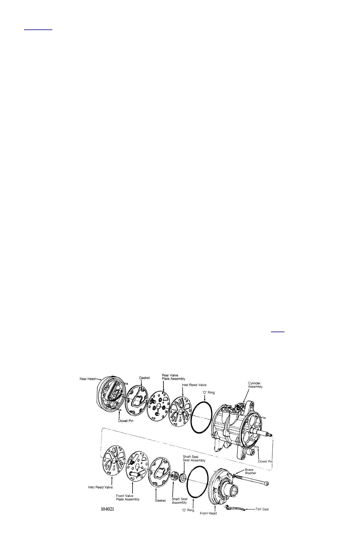
3. Using Key Remover (T81P-19623-NH), remove key from compressor shaft. Remove front head-to-compressor retaining bolts. Remove
front head. Front valve plate assembly, inlet reed valve and shaft seal assembly come off with front head. See
Fig. 1
.
4. Remove dowel pins from front head. Lift inlet reed valve assembly from front head. Using Valve Plate Remover (T81P-19623-B),
remove front valve plate assembly from front head. Remove shaft seal assembly and felt seal from front head.
5. Place front head on cardboard. Using hammer and Shaft Seal Seat Remover (T81P-19623-OH), drive shaft seal seat from front head.
Clean components with solvent.
CAUTION:
When discharging air conditioning system, use only approved refrigerant recovery/recycling
equipment. Make every attempt to avoid discharging refrigerant into the atmosphere.
CAUTION:
DO NOT drive clutch plate on compressor. Use clutch plate installer to prevent damaging
compressor. DO NOT tighten compressor shaft nut with air tools.