Ford F150 Pickup. Manual - part 694


  Index      Ford     Ford F150 Pickup - service and repair manual 2003 year


Search            


Content   ..  692  693  694  695   ..


Ford F150 Pickup. Manual - part 694


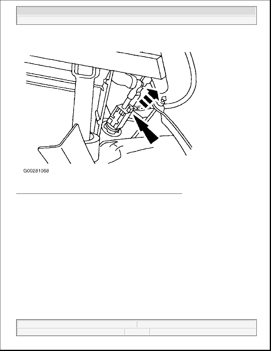
Fig. 13: Disconnecting Clutch Pedal Position Switch Electrical Connector 
Courtesy of FORD MOTOR CO. 


2003 Ford Pickup F150 

2003 STARTING & CHARGING SYSTEMS Starters - F150 Pickup


Fig. 14: Removing Clutch Pedal Position Switch Plastic Retainer 
Courtesy of FORD MOTOR CO. 

DIGITAL TRANSMISSION RANGE SENSOR 

Removal (With 4R100 Transmission) 

Place transmission in Neutral and set parking brake. Disconnect battery ground cable. Raise and support 
vehicle. Disconnect DTR sensor electrical connector. Disconnect shift cable at transmission. Remove 2 bolts 
from Digital Transmission Range (DTR) sensor and remove sensor. 

Installation 

Install DTR sensor and finger tighten 2 bolts. Ensure transmission is in Neutral. Using DTR sensor Adjusting 
Gauge (307-351), align DTR sensor. See Fig. 2 . Tighten bolts to specification. See TORQUE 
SPECIFICATIONS
 . Reconnect shift cable and electrical connector.

CAUTION: When battery is disconnected, vehicle computer and memory systems 

may lose memory data. Driveability problems may exist until computer 
systems have completed a relearn cycle. See COMPUTER RELEARN 
PROCEDURES article in GENERAL INFORMATION before disconnecting 
battery.

NOTE:

Transmission Range Sensor Alignment Gauge (307-351) is required for this 
procedure. See Fig. 1 .


2003 Ford Pickup F150 

2003 STARTING & CHARGING SYSTEMS Starters - F150 Pickup


Removal (With 4R70W Transmission) 

1. Disconnect the battery ground cable. Raise and support vehicle. Disconnect the Digital Transmission 

Range (DTR) sensor electrical connector. See Fig. 4 . Do not pry on the swivel tube to disconnect the 
transmission shift linkage.  

2. Disconnect the manual lever shift control cable. Remove the manual control lever nut and discard. 

Remove the lever. Remove the DTR sensor bolts and the DTR sensor.  

Installation 

1. Install the DTR sensor and loosely install the bolts. Manual shift lever must be in the neutral position. 

Using the special tool, align the DTR sensor slots. The tool is designed to fit snug. Tighten the bolts to 
specification. See TORQUE SPECIFICATIONS .  

2. Install and position the manual control lever. Install a new manual lever shaft outer nut and torque to 

specification. With the manual lever in overdrive connect the shift lever control cable. Install the DTR 
sensor electrical connector. Lower the vehicle. Connect the battery ground cable.  

STARTER RELAY 

Removal & Installation 

Disconnect the battery ground cable. Remove the insulator cap from the solenoid relay switch terminal. 
Disconnect the engine control sensor wiring terminal. See Fig. 15 . Remove the solenoid relay switch terminal 
nuts. Remove the wiring. Remove the solenoid relay switch bolts. Remove the solenoid relay switch. To install, 
reverse removal procedure. Tighten bolts/nuts to specification. See TORQUE SPECIFICATIONS .

NOTE:

When the battery is disconnect and reconnected, some abnormal drive 
symptoms may occur while the vehicle relearns its adaptive strategy. The 
vehicle may need to be driven 10 miles (16 km) or more to relearn the strategy.

WARNING:

When performing maintenance on the starting system be aware that 
heavy gauge leads are connected directly to the battery. Make sure 
protective caps are in place when maintenance is complete. Failure to 
follow this procedure may result in personal injury.


2003 Ford Pickup F150 

2003 STARTING & CHARGING SYSTEMS Starters - F150 Pickup


Fig. 15: Identifying Starter Relay Wiring 
Courtesy of FORD MOTOR CO. 

STARTER MOTOR 

Removal & Installation 

Disconnect negative battery cable. Raise and support vehicle. Remove starter solenoid terminal cover. 
Disconnect starter solenoid wire connections. Remove starter motor mounting nut and ground cable. Remove 
starter motor mounting bolts. Remove starter motor. To install, reverse removal procedure. Ensure negative 
battery cable is installed in proper location. Tighten fasteners to specification. See TORQUE 
SPECIFICATIONS
 . 

STARTER MOTOR SPECIFICATIONS 

STARTER MOTOR SPECIFICATIONS 

Application

Specification

Cranking Speed (Normal Load)

140-220 RPM

Current Draw

Normal Load

130-220 Amps


2003 Ford Pickup F150 

2003 STARTING & CHARGING SYSTEMS Starters - F150 Pickup


Content   ..  692  693  694  695   ..