Ford F150 Pickup. Manual - part 340


  Index      Ford     Ford F150 Pickup - service and repair manual 2003 year


Search            


Content   ..  338  339  340  341   ..


Ford F150 Pickup. Manual - part 340


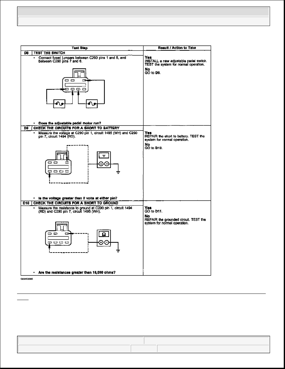
Fig. 8: Pinpoint Test D Adjustable Brake Pedal Does Not Operate/Does Not Operate Correctly Step (D8-
D10)
 
Courtesy of FORD MOTOR CO. 


2003 Ford Pickup F150 

2003 GENERAL INFORMATION Brake System - General Information - F150 Pickup


Fig. 9: Pinpoint Test D Adjustable Brake Pedal Does Not Operate/Does Not Operate Correctly Step 
(D11)
 
Courtesy of FORD MOTOR CO. 

Component Tests 

Brake Booster 

1. Check the hydraulic brake system for leaks or insufficient fluid.  

2. With the transmission (7003) in NEUTRAL, stop the engine (6007) and apply the parking brake control 

(2780). Apply the brake pedal several times to exhaust all vacuum in the system.  

3. Apply the brake pedal (2455) and hold it in the applied position. Start the engine. If the vacuum system is 

operating, the brake pedal will tend to move downward under constant foot pressure. If no motion is felt, 
the power brake booster (2005) system is not functioning. Continue the test with the following steps.  

4. Remove the vacuum booster hose (2A047) from check valve connection. Manifold vacuum must be 

available at the check valve end of the vacuum booster hose with the engine at idle speed and the 
transmission in NEUTRAL. If the manifold vacuum is available to the power brake booster, connect the 
vacuum booster hose to the power brake booster check valve and repeat Steps 2 and 3 above.  

5. Check and if no downward movement of the brake pedal is felt, install a new power brake booster.  

6. Operate the engine a minimum of 10 seconds at fast idle. Stop the engine, and let the vehicle stand for 10 

minutes. Then apply the brake pedal with approximately 89 N (20 lbs) of force. The brake pedal feel 
should be the same as that noted with the engine operating. If the brake pedal feels hard (no power assist), 
install a new check valve and retest. If the brake pedal feels spongy, bleed the hydraulic system to remove 
air. For additional information, refer to BLEEDING - SYSTEM.  

Check Valve 

The function of the power brake booster check valve (2365) is to allow manifold vacuum to enter the power 
brake booster and prevent the escape of vacuum in case manifold vacuum is lost during sustained full throttle 


2003 Ford Pickup F150 

2003 GENERAL INFORMATION Brake System - General Information - F150 Pickup


operation. 

To test the function of the power brake booster check valve: 

z

Start and run the engine for at least 10 seconds.  

z

Operate the brake pedal to check for power assist.  

z

Disconnect the vacuum booster hose from the power brake booster. Do not remove the power brake 
booster check valve from the power brake booster.  

z

There should be enough vacuum retained in the power brake booster for at least one more power-assisted 
brake operation.  

Brake Master Cylinder 

Normal Conditions 

The following conditions are considered normal and are not indications that the brake master cylinder (2140) is 
in need of repair. 

Condition 1: During normal operation of the brake master cylinder, the fluid level in the brake master cylinder 
reservoir (2K478) will rise during brake application and fall during release. The net fluid level (after brake 
application and release) will remain unchanged. 

Condition 2: A trace of brake fluid will exist on the booster shell below the master cylinder mounting flange. 
This results from the normal lubricating action of the master cylinder bore and seal. 

Condition 3: Fluid level will decrease with pad wear. 

Abnormal Conditions 

Changes in brake pedal feel or travel are indicators that something could be wrong in the brake system. For 
additional information, refer to the SYMPTOM CHART for abnormal condition diagnosis. 

Bypass Condition Test 

To perform this test: 

1. Disconnect the brake lines at the brake master cylinder.  

2. Plug the outlet ports of the brake master cylinder.  

3. Apply the brakes. If brake pedal height cannot be maintained, the brake master cylinder has an internal 

leak and must be rebuilt or a new master cylinder installed.  

Compensator Port Check 

The purpose of the compensator ports in the brake master cylinder is to supply any additional brake fluid 
required by the system due to brake pad (2001) wear and to allow brake fluid returning from the brake lines to 
the brake master cylinder to enter the brake master cylinder reservoir.


2003 Ford Pickup F150 

2003 GENERAL INFORMATION Brake System - General Information - F150 Pickup


The returning brake fluid will cause a slight turbulence in the brake master cylinder reservoir. Turbulence seen 
in the brake master cylinder reservoir upon release of the brake pedal is normal and shows that the 
compensating ports are not plugged. 

GENERAL PROCEDURES 

BLEEDING - COMPONENTS 

Special Tool(s) 

Fig. 10: Special Tool(s) 
Courtesy of FORD MOTOR CO. 

Master Cylinder Priming - In-Vehicle or Bench 

WARNING:

Use of any other than approved DOT 3 brake fluid will cause permanent 
damage to brake components and will render the brakes inoperative.


2003 Ford Pickup F150 

2003 GENERAL INFORMATION Brake System - General Information - F150 Pickup


Content   ..  338  339  340  341   ..