Daewoo Korando. Service manual - part 324
SEAT BELTS 8A-3
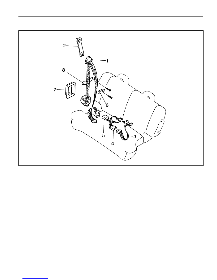
REAR SEAT BELT
1 Seat Belt Assembly (3-point)
2 Seat Belt Stalk Plate Assembly
3 Seat Belt Assembly (2-Point)
4 Webbing Buckle Assembly (Center)
5 Webbing Buckle Assembly (Rear)
6 Webbing Hanger
7 Seat Belt Dust Cover
8 Webbing Guide