Daewoo Korando. Service manual - part 235


  Index      Daewoo     Daewoo Korando - service and repair manual


Search            


Content   ..  233  234  235  236   ..


Daewoo Korando. Service manual - part 235


ANTILOCK BRAKE SYSTEM  4F-9
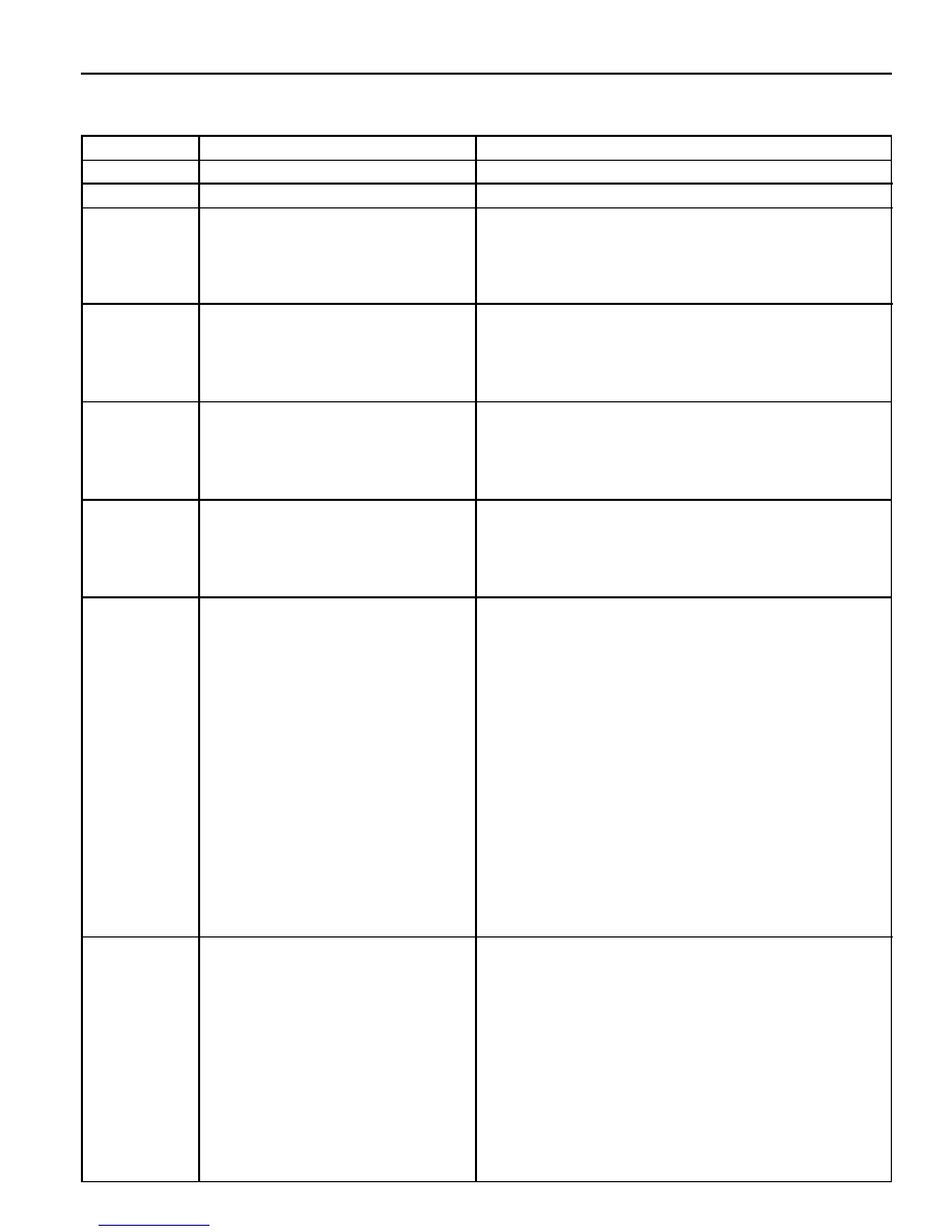
DEFECT CODES

Description

   -

Replace the ECU

l

Check resistance of the wheel speed sensor : 1.280K

W

- 1.920K

W

l

Check wire for ground and open.

l

Replace the sensor.

l

Check resistance of the wheel speed sensor : 1.280K

W

- 1.920K

W

l

Check wire for ground and open.

l

Replace the sensor.

l

Check resistance of the wheel speed sensor : 1.280K

W

- 1.920K

W

l

Check wire for ground and open.

l

Replace the sensor.

l

Check resistance of the wheel speed sensor : 1.280K

W

- 1.920K

W

l

Check wire for ground and open.

l

Replace the sensor.

l

Check wire for ground and open.

l

Check connection of the wheel speed sensor connec-

tor and ECU side connector.

l

Measure air gap between wheel teeth and wheel speed

sensor and check installation of wheel tooth.

(Standard air gap : 0.35 - 1.60 mm)

l

Check output voltage of the sensor by rotating the

wheel 1/2 - 1 revolution per second and shaking sen-

sor wire.

-

When measured by multi - meter (AC) :

output voltage > 70 mV

-

When measured in oscilloscope :

output voltage 

³

 120 mV/P-P

l

Replace the sensor.

l

Check wire for ground and open.

l

Check connection of the wheel speed sensor. con-

nector and ECU side connector.

l

Measure the air gap between wheel teeth and wheel

speed sensor and check installation of wheel tooth.

(Standard air gap : 0.35 - 1.60 mm)

l

Check output voltage of the sensor by rotating the

wheel 1/2 - 1 revolution per second and shaking sen-

sor wire.

-

When measured by multi - meter (AC) :

Defect Code

01

02

03

04

05

06

07

08

Application

Normal

Defective ECU

Front/left Wheel Speed

Sensor (Wire)

Front/right Wheel Speed

Sensor (Wire)

Rear/left Wheel Speed

Sensor (Wire)

Rear/right Wheel Speed

Sensor (Wire)

Front/left Wheel Speed

Sensor (Signal)

Front/right Wheel Speed

Sensor (Signal)

4F-10  ANTILOCK BRAKE SYSTEM

Description

output voltage > 70 mV

-

When measured in oscilloscope :

output voltage 

³

 120 mV/P-P

l

Replace the sensor.

l

Check wire for ground and open.

l

Check connection of the wheel speed sensor con-

nector and ECU side connector.

(Standard air gap : 0.15 - 1.20 mm)

l

Check output voltage of the sensor by rotating the

wheel 1/2 - 1 revolution per second and shaking sen-

sor wire.

-

When measured by multi - meter (AC) :

output voltage > 70 mV

-

When measured in oscilloscope :

output voltage 

³

 120 mV/P-P

l

Replace the sensor.

l

Check wire for ground and open.

l

Check connection of the wheel speed sensor con-

nector and ECU side connector.

l

Measure air gap between wheel teeth and wheel

speed sensor and check installation of wheel tooth.

(Standard air gap : 0.15 - 1.20 mm)

l

Check output voltage of the sensor by rotating the

wheel 1/2 - 1 revolution per second and shaking sen-

sor wire.

-

When measured by multi - meter (AC) :

output voltage > 70 mV

-

When measured in oscilloscope :

output voltage 

³

 120 mV/P-P

l

Replace the sensor.

l

Check number of teeth on the wheel rotor and its

condition.

-

Number of teeth : 52

l

Check valve relay voltage.

l

Check connection of connector and terminals in the

ECU and hydraulic modulator.

l

Check ground.

l

Check terminals for open or short.

(When connector is removed)

l

Replace the hydraulic modulator.

Defect Code

09

10

11

12

Application

Rear/left Wheel Speed

Sensor (Signal)

Rear/right Wheel Speed

Sensor (Signal)

Wheel Rotor

Valve Relay

ANTILOCK BRAKE SYSTEM  4F-11

Description

l

Check each valve by using SCANER's solenoid valve

overriding function.

l

Check connection of connector and terminals in the

ECU hydraulic modulator.

l

Check each valve by using SCANER's solenoid valve

overriding function.

l

Check connection of connector and terminals in the

ECU hydraulic modulator.

l

Check terminals for open or short.

(When connector is removed)

l

Replace the hydraulic modulator.

l

Check each valve by using SCANER's solenoid valve

overriding function.

l

Check connection of connector and terminals in the

ECU hydraulic modulator.

l

Check terminals for open or short.

(When connector is removed)

l

Replace the hydraulic modulator.

l

Check each valve by using SCANER's solenoid valve

overriding function.

l

Check connection of connector and terminals in the

ECU hydraulic modulator.

l

Check terminals for open or short.

(When connector is removed)

l

Replace the hydraulic modulator.

l

Check each valve by using SCANER's solenoid valve

overriding function.

l

Check connection of connector and terminals in the

ECU hydraulic modulator.

l

Check terminals for open or short.

(When connector is removed)

l

Replace the hydraulic modulator.

l

Check each valve by using SCANER's solenoid valve

overriding function.

l

Check connection of connector and terminals in the

ECU hydraulic modulator.

l

Check terminals for open or short.

(When connector is removed)

l

Replace the hydraulic modulator.

l

Check each valve by using SCANER's solenoid valve

overriding function.

l

Check connection of connector and terminals in the

ECU hydraulic modulator.

l

Check terminals for open or short.

Application

Front / left INLET Valve

Front / left OUTLET Valve

Front / right INLET Valve

Front / right OUTLET Valve

Rear / left INLET Valve (ABD)

Rear / left OUTLET Valve

Rear / right INLET Valve

Defect Code

13

14

15

16

17

18

19

4F-12  ANTILOCK BRAKE SYSTEM

Description

(When connector is removed)

l

Replace the hydraulic modulator.

l

Check each valve by using SCANER's solenoid valve

overriding function.

l

Check connection of connector and terminals in the

ECU hydraulic modulator.

l

Check terminals for open or short.

(When connector is removed)

l

Replace the hydraulic modulator.

l

Check solenoid internal resistance of the prime(ASV)

valve and pilot valve(USV) : 8.04 - 9.04 

W

l

Check each valve by using SCANER's solenoid valve

overriding function.

l

Check connection of connector and terminals in the

ECU and hydraulic modulator.

l

Check terminals for open or short.

(When connector is removed)

l

Replace the hydraulic modulator.

l

Check each valve by using SCANER's pump motor

overriding function.

l

Check resistance between pump motor ground ter-

minal and battery negative terminal : total resistance

should be less than 15 m

W.

l

Check body ground location.

l

Check relay supply voltage : IGN on : 11 - 14 V

l

Relay coil internal resistance : 70 - 80 

W

l

Replace the hydraulic modulator.

l

Check by using SCANER's stop lamp switch diagnos-

ing function from sensor value output function.

l

Check connection of ECU connector side stop lamp

switch terminal.

l

Check resistance of the stop lamp switch.

-

Each end resistance value of the switch

Application

Rear / right OUTLET Valve

Function and Response of The

Valve

Function and Response of The

Valve

Motor Relay / Circulation Pump

Stop Lamp Switch

Defect Code

20

21

22

24

27


Content   ..  233  234  235  236   ..