Daewoo Korando. Service manual - part 218


  Index      Daewoo     Daewoo Korando - service and repair manual


Search            


Content   ..  216  217  218  219   ..


Daewoo Korando. Service manual - part 218


FRONT DRIVE AXLE  3A-19

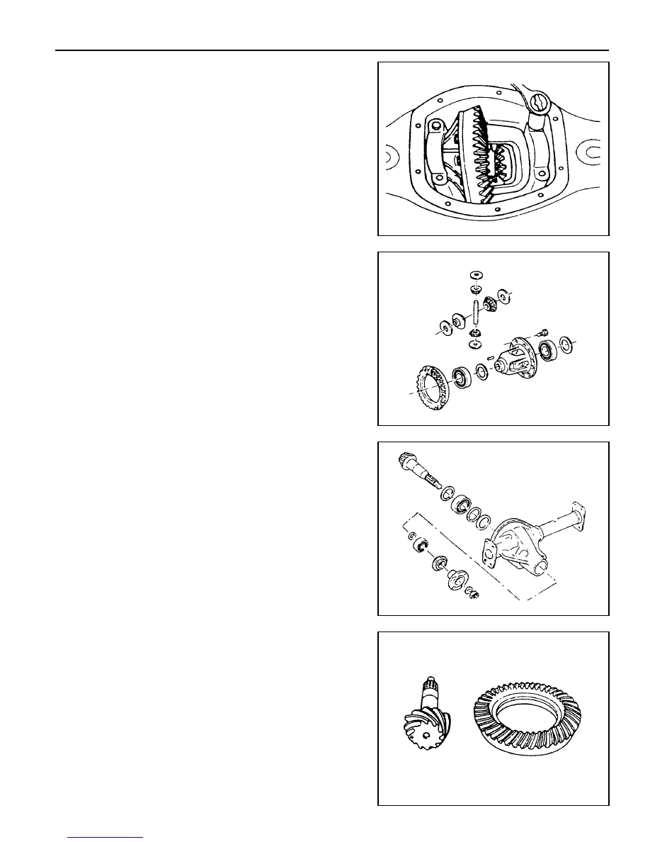
5. Unscrew the bearing cap bolts and remove the bearing caps.

Pull out the differential carrier assembly.

Notice

Place alignment marks on the bearing cap not to change
the caps before removal. When pulling out the differential
carrier assembly, be careful not to damage the axle housing.

6. Disassemble the parts of the differential carrier assembly.

7. Remove the drive pinion lock nut. Disassemble the parts of

the drive pinion.

Assembly Procedure

1. Clean the all parts and check the followings :

l

Check the ring gear and drive pinion for wear and
damage. If damaged, replace it as a set.

l

Check the bearing for sticks, wear, noise and turning
resistance.

l

Check the side gear, pinion, pinion shaft and thrust
washer for wear and damage.

l

Check the differential carrier for crack and wear (bearing
contact surface). Check the gear case for crack.

3A-20  FRONT DRIVE AXLE

2. Assemble the parts of the drive pinion.

3. Assemble the parts of the differential carrier.

4. Measure backlash of the side gear and pinion.

5. Install the differential carrier assembly into the axle housing.

Notice

Be careful not to change the caps. Be sure to keep the
original position of the caps.

Tightening Torque of the

Lock Nut

240 - 310 Nm

Tightening Torque of the

Ring Gear Bolts

75 - 90 Nm

Standard

0 - 0.05 mm

Tightening Torque of the

Bearing Cap Bolts

48 - 69 Nm

FRONT DRIVE AXLE  3A-21

6. Measure backlash of the drive pinion and ring gear.

7. Install the axle housing cover.

8. Assemble the parts of the front axle shaft and housing

mounting bracket.

Notice

Apply grease to the oil seal rib.

9. Align the axle shaft and differential carrier spline and insert

the axle shaft. Assemble the axle housing mounting bracket
to the axle housing.

Specified Value

0.13 - 0.20 mm

Tightening Torque

39 - 46 Nm

Tightening Torque

55 - 65 Nm

3A-22  FRONT DRIVE AXLE

Inspection of Ring Gear Tooth Contact Pattern

Normal Contact

Apply gear-marking compound (prussian blue / red lead) on
the ring gear teeth. Rotate the ring gear and check the tooth
contact pattern.

Abnormal Contact

Tooth Contact pattern

Possible Cause

Remedy

1. Heel Contact

2. Toe Contact

3. Face Contact

4. Flank Contact

Insufficient backlash (little)

l

Tooth can be damaged
or broken under heavy
load

Excessive backlash (much)

l

Drive pinion shaft is apart
from the ring gear

l

Noise can be occurred

Insufficient backlash (much)

l

Gear contacts on the low
flank

l

Gear can be damaged or
worn

l

Noise can be occurred

Adjust backlash(Decrease backlash)

l

Select proper shim(s) to move the
drive pinion toward the ring gear
(toward toe)

Adjust backlash(Increase backlash)

l

Select proper shim(s) to move the
drive pinion against the ring gear
(toward heel)

Adjust backlash(Increase pinion shim)

l

Move the drive pinion toward the ring
gear (toward center of ring gear)

Adjust backlash(Decrease pinion shim)

l

Move the ring gear toward the drive
pinion (toward ring gear center line)

Excessive backlash (little)

l

Noise can be occurred


Content   ..  216  217  218  219   ..