Daewoo Korando. Service manual - part 173


  Index      Daewoo     Daewoo Korando - service and repair manual


Search            


Content   ..  171  172  173  174   ..


Daewoo Korando. Service manual - part 173


1F2-56  M161 ENGINE CONTROLS

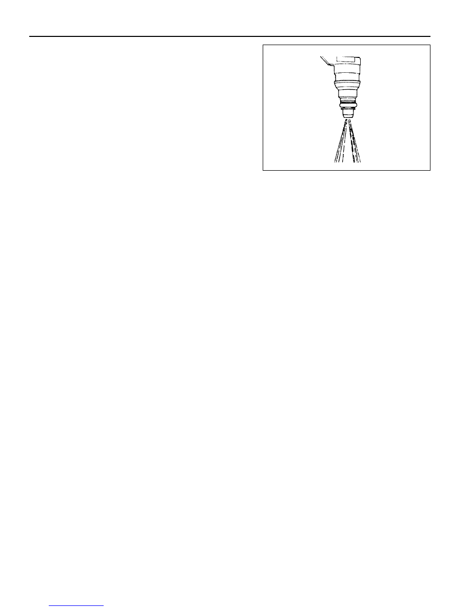
The Injector Spray Pattern Check

1. Connect the test box (129 589 00 21 00) to the ECU.

2. Disconnect the connector from connector.

3. Disconnect the fuel distributor and injector with a unit from

engine without removing the fuel supply and return line.

Notice

Prepare the beaker for taking the poping fuel.

4. Connect either end of shop made cable to the injector.

5. Connect the other end of shop made cable to the No.11

and No.5 terminal of the test box.

6. Turn the ignition switch to "ON" position.

7. Check the injector for normal spray pattern as shown in the

figure. Check injector for leaks or later drops.

Notice

Refer to fuel injector test of engine diagnosis in this section
for detailed information.

M161 ENGINE CONTROLS  1F2-57

FUEL FILTER

1 Fuel Filter
2 Outlet

Removal & Installation Procedure

1. Open the fuel tank cap and remove the fuel tank pressure.

2. Remove the fuel out (2) and in (3).

Installation Notice

Notice

Place the fuel pump pad. There may be a corrosion due to
the contact between the fuel filter and the bracket.

4. Check for leaks by operating the engine.

Notice

Installation should follow the removal procedure in the
reverse order.

3. Remove the mounting bracket bolt (4) and remove the fuel

filter (1).

Installation Notice

3 Inlet

Tightening Torque

25 - 30 Nm

Tightening Torque

4 - 8 Nm

1

3

2

1F2-58  M161 ENGINE CONTROLS

FUEL PUMP

Requirements for Fuel Pump

Item

Specified Value

Item

Specified Value

System pressure

3.8 bar

Minimum delivery at 8V

30 Litre/Hr

Maximum pressure

8.5 bar (12 V)

Minimum amount

of fuel supply

 114 Liter/Hr (12 V, 3.8 bar, -

30 ~ +70°C)

Minimum pressure

5.0 bar (12 V)

Maximum allowable current

7.5 A

Nominal voltage

12 V

Ambient temperature

-30 ~ +70°C

1 Reservoir Tank
2 Fuel Sensor (float/arm)
3 Resistance
4 Wiring Connector
5 Fuel Supply Pipe
7 Float

10 Flange and Harness Assembly

11 Fuel Pump

12 Spring
13 Thermister Housing
14 Thermister
15 Resistor Card and Wiper
16 Float Arm

Operating voltage

8 V

Maximum amount

of fuel supply

165 Liter/Hr (12V, 3.8 bar,

-30 ~ +70°C)

M161 ENGINE CONTROLS  1F2-59

1

2

3

4

1 Fuel Pump Connector Wiring
2 Fuel Return Pipe
3 Fuel Supply Pipe
4 Bolts

5 Fuel Return Pipe
6 Fuel Supply Pipe
7 Float
8 Ground Stud (Sender "-")

COLOR

Pump "+"

Thermister "+"

Ground

Sender Unit "+"

USE

Harness Location & Connector

A

B

C

D

2.0 BR

0.5 W

2.0 B

0.5 RY


Content   ..  171  172  173  174   ..