Daewoo Korando. Service manual - part 67


  Index      Daewoo     Daewoo Korando - service and repair manual


Search            


Content   ..  65  66  67  68   ..


Daewoo Korando. Service manual - part 67


1B2-90  M161 ENGINE MECHANICAL

Tools Required

001 589 72 21 00

Torqued Wrench

000 589 04 14 00

Clamping Strap

Removal Procedure

1. Unscrew the connecting rod bolt (3) and remove the cap.

2. Remove the connecting rod and the piston upward.

Notice

Make sure that the bearing cap and shell are not changed
each other.

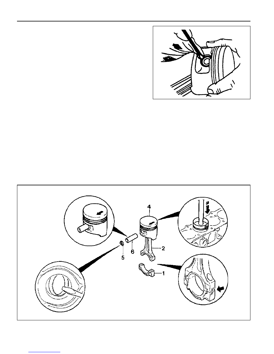
3. Remove the snap ring (5) and pull out the piston pin (6).

Notice

Remove the snap ring using a clean cloth as shown in the
right picture so that the piston, piston ring, and the snap
ring don’t get damaged.

Installation Procedure

M161 ENGINE MECHANICAL  1B2-91

1. Check the piston ring gap and apply the engine oil to the

piston pin and the connecting rod bushing.

2. Connect the piston and the connecting rod by pressing in

the piston pin (6) and install the snap ring to the groove.

3. Clean the cylinder bore, connecting rod bearing journal,

connecting rod bearing shell and the piston and coat them
with engine oil.

4. Install the piston ring using the tensioning strap(000 589

04 14 00).

5. Install the piston so that the arrow on the piston head faces

to the forward of the vehicle.

6. After aligning the connecting rod and the bearing cap mark

(// or a number), tighten the bolts.

    Installation Notice

Tightening Torque

1st step 35-45 Nm

2nd step 90°+5°

Apply the engine oil to the bearing cap upper and lower
bearing shells.

7. Check if the crankshaft rotates without any trouble by rotating

it.

1B2-92  M161 ENGINE MECHANICAL

CONNECTING ROD

Preceding Work : Removal of piston

1 Connecting Rod Bushing
2 Oil Gallery
3 Balance Weight
4 Connecting Rod Bolt

(M9 x 52, 8 pieces) ............ 1st step 40 Nm

2nd step 90°

5 Fit Sleeve
6 Upper Connecting Rod Bearing
7 Lower Connecting Rod Bearing
8 BearingShell Lug
9 Marking [Indication(//) or Numbers]

Service Data Standard

Distance (L) from The Connecting Rod Bearing to Bushing Bore Center

Width of The Connecting Rod (B) at Bearing Bore

Width of The Connecting Rod (b) at Bushing Bore

Basic Bore at The Bearing Shell (D1)

Basic Bore at The Bushing (d1)

Bushing Inner Diameter (d)

Clearance Between The Piston Pin and The Bushing

Peak-to-valley Height of Connecting Rod Bushing on Inside

Permissible Wwist of Connecting Rod Bearing Bore to

Connecting Rod Bushing Bore

Permissible Deviation of Axial Paralleism of Connecting Rod

Bearing Bore to Connecting Rod Bushing Bore

Permissible Deviation of Axial Paralleism of Connecting Rod Bearing Bore from

Concentricity

Permissible Difference of Each Connecting Rod in Weight

E20 : 154 mm

E23 : 149 ± 0.05 mm

21.940 - 22.000 mm

21.940 - 22.000 mm

51.600 - 51.614 mm

24.500 - 24.571 mm

22.007 - 22.013 mm

0.007 - 0.018 mm

0.005 mm

0.1/100 mm

0.045/100 mm

0.01 mm

0.4 g

M161 ENGINE MECHANICAL  1B2-93

Inspection

1. Measure the basic bore of the connecting rod bearing.

Notice

If the basic bore exceeds the value of 51.614mm, replace
the bearing or check the connecting rod.

2. Check connecting rod bolts.

3. Check the assembly mark(indication // or number:arrow) of

the connecting rods and the bearing cap when installing.

Notice

l

Make sure it doesn’t exceed over 4g with other

connecting rods when replacing the connecting rods.

l

Check if the connecting rod and the bearing cap are

accurately seated on the groove when replacing the
bearing.

Notice

If the length exceeds max. length, replace it.

Length When New (L)

Max. Length (L)

Tightening Torque

51.7 - 52 mm

52.9 mm

1st step 40 + 5 Nm

2nd step 90°+10°


Content   ..  65  66  67  68   ..