Daewoo Matiz (2003 year). Service manual - part 192


  Index      Daewoo     Daewoo Matiz - service and repair manual 2003 year


Search            


Content   ..  190  191  192  193   ..


Daewoo Matiz (2003 year). Service manual - part 192


7A – 26 HEATING AND VENTILATION SYSTEM

D18A531B

Installation Procedure

1. Install the blower module with the nuts.
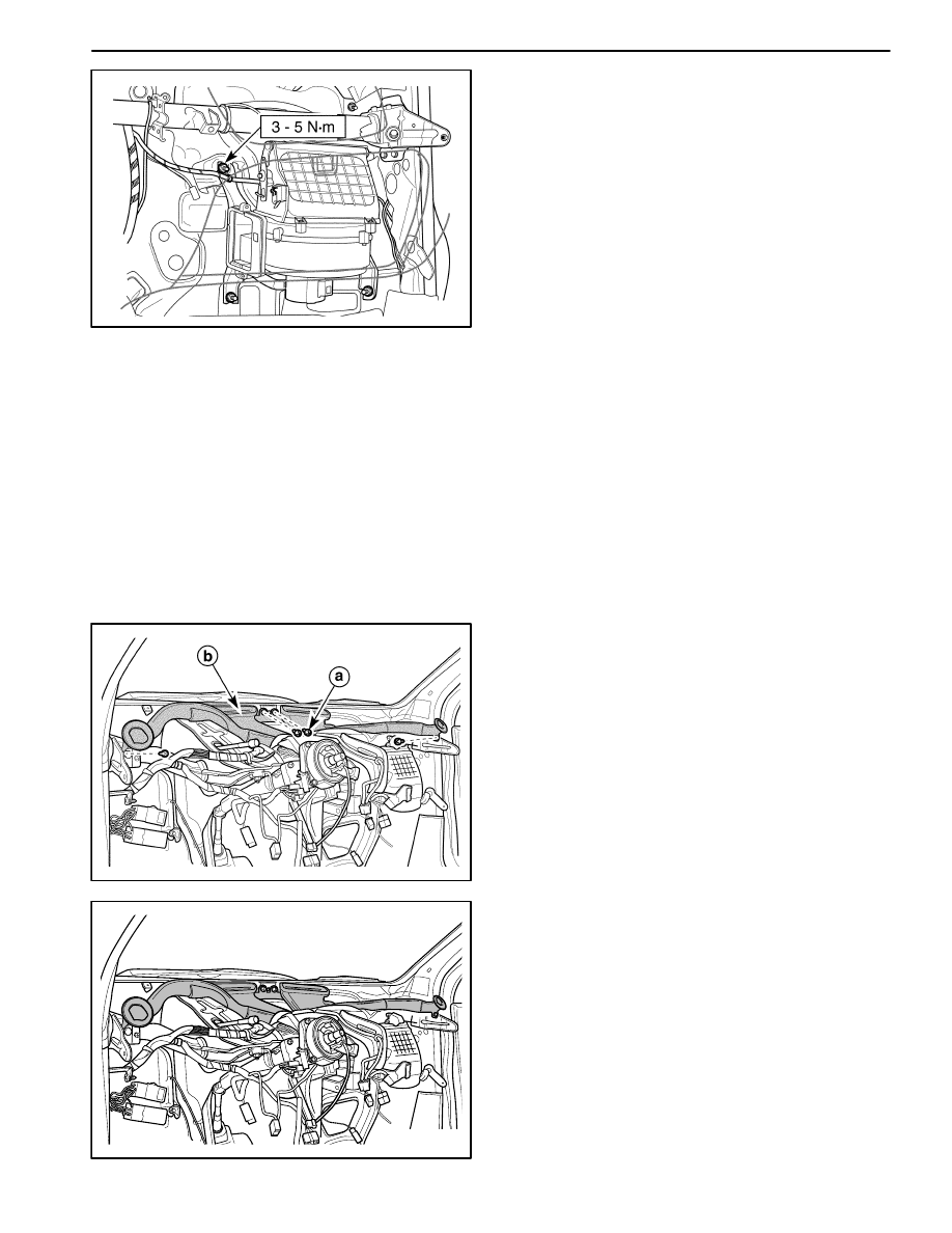
Tighten

Tighten the blower module retaining nuts to 3–5 N

S

m

(27–44 lb-in).

2. Connect the wiring harness.

3. Connect the blower motor connector. Refer to “Blow-

er Motor and Cooling Hose” in this section.

4. Install the blower resistor. Refer to “Blower Resistor”

in this section.

5. Install the evaporator on the vehicle equipped with

A/C. Refer to Section 7B, Manual Control Heating,
Ventilation, and Air Conditioning System
.

6. Install the heater module–to–blower module connec-

tion tube on the vehicle not equipped with A/C. Refer
to “Heater Module” in this section.

7. Install the glove box to the instrument panel. Refer to

Section 9E, Instrumentation/Driver Information.

D108A532

DEFROSTER DUCT AND HOSES

(Left–Hand Drive Shown, Right–Hand
Drive Similar)

Removal Procedure

1. Remove the instrument panel. Refer to Section 9E,

Instrumentation/Driver Information.

2. Remove the defroster duct and hoses retaining

screws.

a. Retaining screw.

3. Remove the defroster duct and hoses.

b. Defroster duct and hoses.

D108A533

Installation Procedure

1. Install the defroster duct and hoses with the screws.

2. Install the instrument panel. Refer to Section 9E, In-

strumentation/Driver Information.

HEATING AND VENTILATION SYSTEM 7A – 27

D18A534A

VENTILATION DUCT

(Left–Hand Drive Shown, Right–Hand
Drive Similar)

Removal Procedure

1. Remove the instrument panel. Refer to Section 9E,

Instrumentation/Driver Information.

2. Remove the ventilation duct retaining screws.

a. Retaining screw.

3. Remove the ventilation duct.

b. Ventilation duct.

D108A535

Installation Procedure

1. Install the ventilation duct with the screws.

2. Install the instrument panel. Refer to Section 9E, In-

strumentation/Driver Information.

7A – 28 HEATING AND VENTILATION SYSTEM

UNIT REPAIR

D108A701

HEATER CORE

Disassembly Procedure

1. Remove the heater module. Refer to “Heater Module”

in this section.

2. Remove the heater core.

D

Remove the heater core cover (1).

D

Remove the heater core (2).

D108A702

Assembly Procedure

1. Install the heater core to the heater module.

2. Install the heater core cover.

3. Install the heater module. Refer to “Heater Module” in

this section.

HEATING AND VENTILATION SYSTEM 7A – 29

SPECIFICATIONS

GENERAL SPECIFICATIONS

ÁÁÁÁÁÁÁÁÁÁÁÁÁÁÁÁÁÁÁ

ÁÁÁÁÁÁÁÁÁÁÁÁÁÁÁÁÁÁÁ

Application

ÁÁÁÁÁÁ

ÁÁÁÁÁÁ

Unit

ÁÁÁÁÁÁÁÁÁÁÁÁ

ÁÁÁÁÁÁÁÁÁÁÁÁ

Description

ÁÁÁÁÁÁÁÁÁÁÁÁÁÁÁÁÁÁÁ

ÁÁÁÁÁÁÁÁÁÁÁÁÁÁÁÁÁÁÁ

Maximum Heating Capacity

ÁÁÁÁÁÁ

ÁÁÁÁÁÁ

cal/h

ÁÁÁÁÁÁÁÁÁÁÁÁ

ÁÁÁÁÁÁÁÁÁÁÁÁ

7,300

ÁÁÁÁÁÁÁÁÁÁ

ÁÁÁÁÁÁÁÁÁÁ

ÁÁÁÁÁÁÁÁÁÁ

ÁÁÁÁÁÁÁÁÁÁ

1 st

ÁÁÁÁÁÁ

ÁÁÁÁÁÁ

ÁÁÁÁÁÁÁÁÁÁÁÁ

ÁÁÁÁÁÁÁÁÁÁÁÁ

2.25 – 2.75

ÁÁÁÁÁÁÁÁÁÁ

ÁÁÁÁÁÁÁÁÁÁ

ÁÁÁÁÁÁÁÁÁÁ

ÁÁÁÁÁÁÁÁÁÁ

2 nd

ÁÁÁÁÁÁ

ÁÁÁÁÁÁ

ÁÁÁÁÁÁÁÁÁÁÁÁ

ÁÁÁÁÁÁÁÁÁÁÁÁ

1.08 – 1.32

ÁÁÁÁÁÁÁÁÁÁ

ÁÁÁÁÁÁÁÁÁÁ

Blower Motor Resistance

ÁÁÁÁÁÁÁÁÁÁ

ÁÁÁÁÁÁÁÁÁÁ

3 rd

ÁÁÁÁÁÁ

ÁÁÁÁÁÁ

ÁÁÁÁÁÁÁÁÁÁÁÁ

ÁÁÁÁÁÁÁÁÁÁÁÁ

0.36 – 0.44

ÁÁÁÁÁÁÁÁÁÁ

ÁÁÁÁÁÁÁÁÁÁ

ÁÁÁÁÁÁÁÁÁÁ

ÁÁÁÁÁÁÁÁÁÁ

4 th

ÁÁÁÁÁÁ

ÁÁÁÁÁÁ

ÁÁÁÁÁÁÁÁÁÁÁÁ

ÁÁÁÁÁÁÁÁÁÁÁÁ

FASTENER TIGHTENING SPECIFICATIONS

ÁÁÁÁÁÁÁÁÁÁÁÁÁÁÁÁÁÁ

ÁÁÁÁÁÁÁÁÁÁÁÁÁÁÁÁÁÁ

Application

ÁÁÁÁÁÁÁ

ÁÁÁÁÁÁÁ

N

S

m

ÁÁÁÁÁÁ

ÁÁÁÁÁÁ

Lb-Ft

ÁÁÁÁÁÁÁ

ÁÁÁÁÁÁÁ

Lb-In

Heater Module Nuts

3 – 5

27 – 44

Blower Module Nuts

3 – 5

27 – 44


Content   ..  190  191  192  193   ..