Daewoo Matiz (2003 year). Service manual - part 69


  Index      Daewoo     Daewoo Matiz - service and repair manual 2003 year


Search            


Content   ..  67  68  69  70   ..


Daewoo Matiz (2003 year). Service manual - part 69


1F – 186  ENGINE CONTROLS

MAA1F230

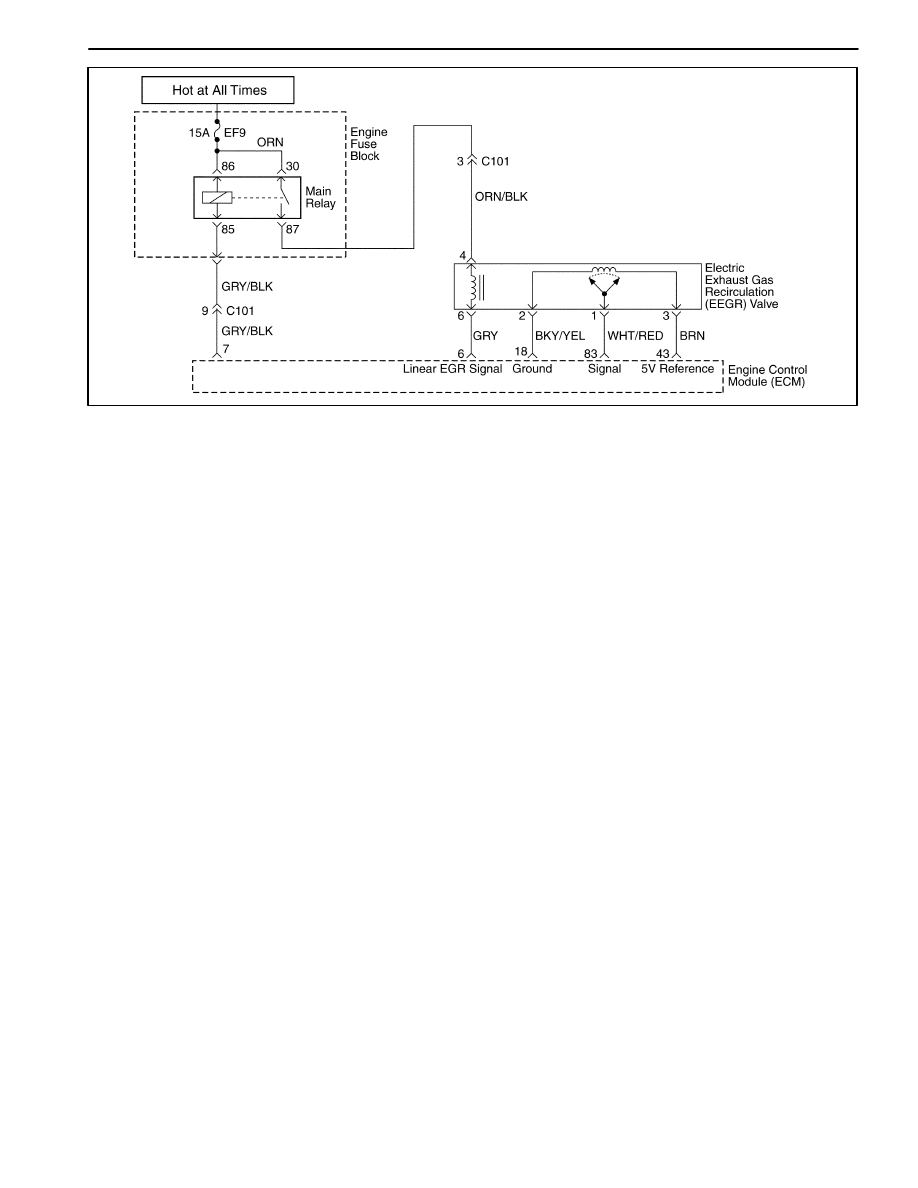
DIAGNOSTIC TROUBLE CODE (DTC) – P1402 ELECTRIC EXHAUST GAS

RECIRCULATION BLOCKED

Circuit Description

An Electric Exhaust Gas Re-circulation (EEGR) system
is used to lower oxides of nitrogen (NOX) emission lev-
els caused by high combustion temperatures. It a ac-
complishes this by feeding small amounts of exhaust
gases back into the combustion chamber. When the air/
fuel mixture is diluted with the exhaust gases, combus-
tion temperatures are reduced.
A EEGR valve is used on this system. The linear EEGR
valve is designed to accurately supply exhaust gases to
the engine without the use of intake manifold vacuum.
The valve controls exhaust flow going into the intake
manifold from the exhaust manifold fhrough an orifice
with a engine control module(ECM) controlled pintle.
The ECM controls the pintle position using inputs from
the Throttle Position (TP) and the Manifold Absolute
Pressure (MAP) sensor. The ECM then commands the
EEGR valve to operate when necessary by controlling
an ignition signal through the ECM. This can be moni-
tored on a scan tool as the Desired EEGR position.

The ECM monitors the results of its command through a
feedback signal. By sending a 5 volt reference and a
ground to the EEGR valve, a voltage signal representing
the EEGR valve pintle position is sent to the ECM. This
feedback signal can also be monitored on a scan tool
and is the actual position of the EEGR pintle. The actual
EEGR position should always be near the commanded
or Desired EEGR position.

ThisDiagnostic Trouble Code(DTC) will detect an open
or short circuit.

Conditions for Setting the DTC

D

Engine Coolant Temperature(ECT) is greater than
80

°

C(176

°

F).

D

Intake Air Temperature(IAT) is greater than 15

°

C

(59

°

F).

D

Manifold Absolute Pressure is greater than 75kPA.

D

The EEGR differential rate is less than 3%.

D

Mass Air Flow is between 92 ~157mg/tdc.

D

Engine Speed Is Between 2,500~2,900rpm.

D

DTCs P0107, P0108, P0112, P0113, P0117, P0118,
P0122, P0123, P0131, P0300, P0335, P0336,
P0341, P0342, P1671, P1672, P1673 are NOT SET.

D

EEGR is disabled.

Action Taken When the DTC Sets

D

The Malfunction Indicator Lamp (MIL) will illuminate.

D

The ECM will record operating conditions at the time
the diagnostic fails. This information will be stored in
the Freeze Frame and Failure Records buffers.

D

A history DTC is stored.

Conditions for Clearing the MIL/DTC

D

The MIL will turn off after four consecutive ignition
cycles in which the diagnostic runs without a fault.

D

A history DTC will clear after 40 consecutive warm-up
cycles without a fault.

D

DTC(s) can be cleared by using the scan tool.

Diagnostic Aids

Due to moisture associated with exhaust systems, the
EEGR valve may freeze and stick in cold weather at
times. After the vehicle is brought into a warm shop for
repairs, the valve warms and the problem disappears.
By watching the Actual EEGR and desired EEGR posi-
tions on a cold vehicle with a scan tool, the fault can be

ENGINE CONTROLS  1F – 187

easily verified. Check the Freeze Frame data to deter-

mine if the DTC set when the vehicle was cold by view-
ing the Engine Coolant Temperature (ECT).

DTC P1402 – Electric Exhaust Gas Recirculation Blocked

Step

Action

Value(s)

Yes

No

1

Perform an Euro On-Board Diagnostic (EOBD)
System Check.
Is the system check complete?

Go to Step 2

Go to

“On-Board
Diagnostic

System Check”

2

1. Start the engine and allow the engine to idle.
2. Install the scan tool.
3. Command the electric exhaust gas recirculation

(EEGR) valve to the specified values.

Does the engine stall or attempt to stall?

50%

Go to Step 5

Go to Step 3

3

1. Turn the ignition switch to LOCK.
2. Remove the EEGR valve assembly.
3. Inspect the EEGR valve, passages and pipe for a

restriction or damage and repair as necessary.

Is a repair necessary?

Go to Step 5

Go to Step 4

4

Replace the EEGR valve.
Is the replacement complete?

Go to Step 5

5

1. Start the engine.
2. Disconnect the battery for the specified time.
3. Drive the vehicle to the specified value.
4. Release the throttle and allow the vehicle to

decelerate to the specified value.

Is the EEGR Decel Filter Values less than the
specified value?

10 secnds

60mph

(97km/h)

20mph

(32km/h)

0mph

Go to Step 3

Go to Step 6

6

1. Using the scan tool, clear the Diagnostic Trouble

Codes (DTCs).

2. Start the engine and idle at normal operating

temperature.

3. Operate the vehicle within the conditions for

setting the DTC as specifiec in the supporting
text.

Does the scan tool indicate that this diagnostic ran
and passed?

Go to Step 7

Go to Step 2

1F – 188  ENGINE CONTROLS

MAA1F230

DIAGNOSTIC TROUBLE CODE (DTC) – P1403 ELECTRIC EXHAUST GAS

RECIRCULATION VALVE FAILURE

Circuit Description

An Electric Exhaust Gas Re-circulation (EEGR) system
is used to lower oxides of nitrogen (NOX) emission lev-
els caused by high combustion temperatures. It a ac-
complishes this by feeding small amounts of exhaust
gases back into the combustion chamber. When the air/
fuel mixture is diluted with the exhaust gases, combus-
tion temperatures are reduced.

A linear EEGR valve is used on this system. The linear
EEGR valve is designed to accurately supply exhaust
gases to the engine without the use of intake manifold
vacuum. The valve controls exhaust flow going into the
intake manifold from the exhaust manifold fhrough an
orifice with a engine control module(ECM) controlled
pintle. The ECM controls the pintle position using inputs
from the Throttle Position (TP) and the Manifold Abso-
lute Pressure (MAP) sensor. The ECM then commands
the EEGR valve to operate when necessary by control-
ling an ignition signal through the ECM. This can be
monitored on a scan tool as the Desired EEGR position.

The ECM monitors the results of its command through a
feedback signal. By sending a 5 volt reference and a
ground to the EEGR valve, a voltage signal representing
the EEGR valve pintle position is sent to the ECM. This
feedback signal can also be monitored on a scan tool
and is the actual position of the EEGR pintle. The actual
EEGR position should always be near the commanded
or Desired EEGR position.

ThisDiagnostic Trouble Code(DTC) will detect an open
or short circuit.

Conditions for Setting THE DTC

D

Engine Coolant Temperature(ECT) is greater than
80

°

C(176

°

F).

D

Intake Air Temperature(IAT) is greater than 15

°

C

(59

°

F).

D

Manifold Absolute Pressure is greater than 75kPA.

D

The open EEGR value is higher than 3%.

D

Mass Air Flow is between 92 ~157mg/tdc.

D

Engine Speed Is Between 2,500~2,900rpm.

D

EEGR potentiometer voltage is less than 0.4V.

D

EEGR potentiometer voltage is higher than 1.75V or
integral term of EEGR controller blocked in high or
low limit.

D

DTCs P0107, P0108, P0112, P0113, P0117, P0118,
P0122, P0123, P0131, P0300, P0335, P0336,
P0341, P0342, P1671, P1672, P1673 are NOT SET.

Action Taken When the DTC Sets

D

The Malfunction Indicator Lamp (MIL) will illuminate.

D

The ECM will record operating conditions at the time
the diagnostic fails. This information will be stored in
the Freeze Frame and Failure Records buffers.

D

A history DTC is stored.

Conditions for Clearing the MIL/DTC

D

The MIL will turn off after four consecutive ignition
cycles in which the diagnostic runs without a fault.

D

A history DTC will clear after 40 consecutive warm-up
cycles without a fault.

D

DTC(s) can be cleared by using the scan tool.

Diagnostic Aids

Due to moisture associated with exhaust systems, the
EEGR valve may freeze and stick in cold weather at
times. After the vehicle is brought into a warm shop for

ENGINE CONTROLS  1F – 189

repairs, the valve warms and the problem disappears.
By watching the Actual EEGR and desired EEGR posi-
tions on a cold vehicle with a scan tool, the fault can be

easily verified. Check the Freeze Frame data to deter-
mine if the DTC set when the vehicle was cold by view-
ing the Engine Coolant Temperature (ECT).

DTC P1403 – Electric Exhaust Gas Recirculation Valve Failure

Step

Action

Value(s)

Yes

No

1

Perform an Euro On-Board Diagnostic (EOBD)
System Check.
Is the system check complete?

Go to Step 2

Go to

“On-Board
Diagnostic

System Check”

2

1. Turn the ignition switch to with the engine OFF.
2. Install the scan tool.
3. Command the electric exhaust gas recirculation

(EEGR) valve to the specified values.

Does the Actual EEGR Position follow the desired
EEGR position?

25%, 50%,

75%, 100%

Go to Step 19

Go to Step 3

3

1. Turn the ignition switch to ON.
2. Disconnect the EEGR valve electrical connector.
3. With a test light connected to B+, probe the

ground circuit to the EEGR valve.

Does the test light illuminate?

Go to Step 4

Go to Step 5

4

1. Connect the test light to ground.
2. Probe the EEGR control circuit at terminal 1 to

the EEGR valve.

3. Command the EEGR valve to the specified

values using a scan tool.

After the command is raised, does the test light glow
brighter, flash or maintain a steady glow?

25%, 50%,

75%, 100%

Go to Step 6

Go to Step 7

5

Repair the open or poor connection in the EEGR
ground circuit.
Is the repair complete?

Go to Step 19

6

With a test light still connected to ground, probe the
signal circuit at terminal 1.
Does the test light illuminate?

Go to Step 8

Go to Step 9

7

With a test light still connected to ground, again
probe the signal circuit without commanding the
EEGR valve with the scan tool.
Does the test light illuminate?

Go to Step 10

Go to Step 11

8

Check the signal circuit for a short to voltage and
repair as necessary.
Is a repair necessary?

Go to Step 19

Go to Step 12

9

With a digital voltmeter (DVM) connected to ground,
probe the 5V reference circuit at terminal 3.
Is the voltage measured near the specified value?

5V

Go to Step 13

Go to Step 14

10

Check the control circuit for a short to battery
voltage and repair as necessary.
Is a repair necessary?

Go to Step 19

Go to Step 12

11

Connect the test light to B+ and again probe the
control circuit at terminal 4.
Does the test light illuminate?

Go to Step 15

Go to Step 16

12

Replace the engine control module (ECM).
Is the replacement complete?

Go to Step 19


Content   ..  67  68  69  70   ..