Daewoo Nubira. Service manual - part 136


  Index      Daewoo     Daewoo Nubira - service and repair manual


Search            


Content   ..  134  135  136  137   ..


Daewoo Nubira. Service manual - part 136


ENGINE CONTROLS  1F – 401

DAEWOO V–121 BL4

FUEL CUTOFF SWITCH

Removal Procedure

1.  Disconnect the negative battery cable.
2.  Remove the passenger front rocker trim panel. Re-

fer to Section 9G, Interior Trim.

3.  Remove the lower B–pillar trim panel. Refer to Sec-

tion 9G, Interior Trim.

4.  Reposition the carpet.

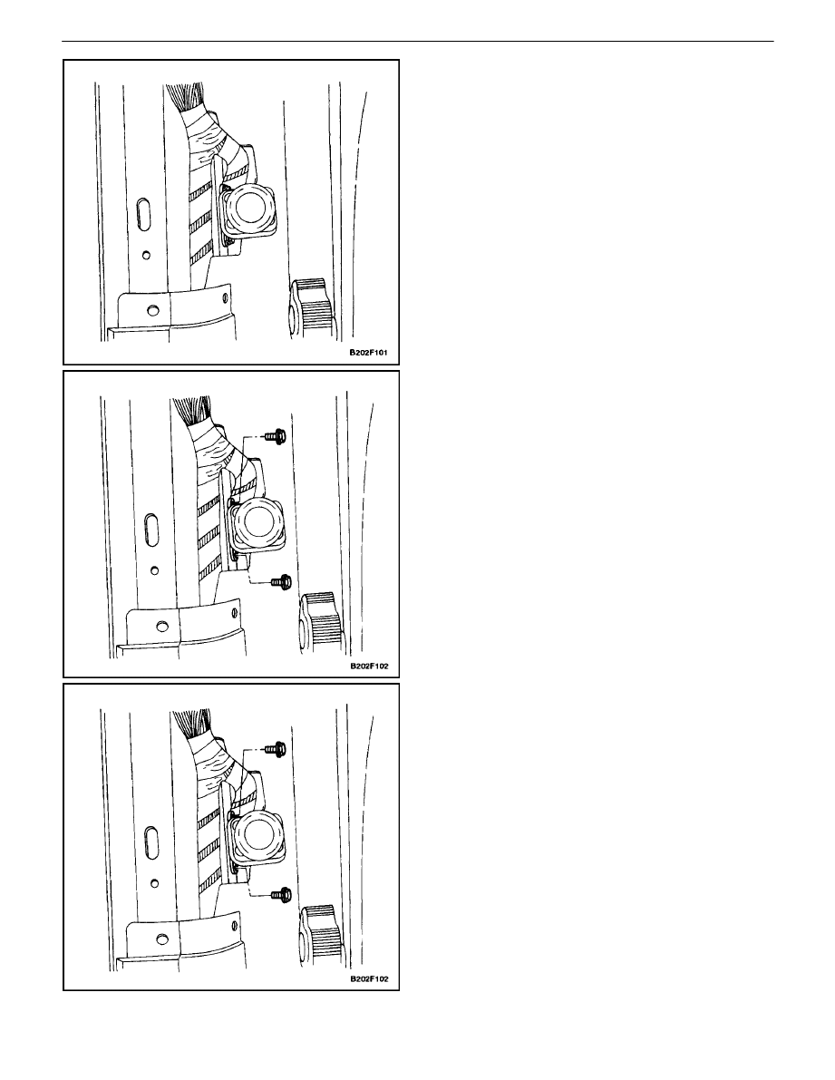
5.  Remove the fuel cutoff switch mounting bolts.
6.  Disconnect the electrical connector at the fuel cutoff

switch.

Installation Procedure

1.  Connect the electrical connector at the fuel cutoff

switch.

2.  Install the fuel cutoff switch mounting bolts.

Tighten

Tighten the fuel cutoff switch mounting bolts to 27 lb–
in (3 N

S

m).

1F – 402

I

ENGINE CONTROLS

DAEWOO V–121 BL4

3.  Reposition the carpet.
4.  Install the lower B–pillar trim panel. Refer to Sec-

tion 9G, Interior Trim.

5.  Install the passenger front rocker trim panel. Refer

to Section 9G, Interior Trim.

6.  Connect the negative battery cable.

Important : The fuel cutoff switch may have to be reset to
enable the vehicle to start.

KNOCK SENSOR

Removal Procedure

1.  Disconnect the negative battery cable.
2.  Remove the intake manifold. Refer toSection 1C,

DOHC Engine Mechanical.

3.  Disconnect the electrical connector at the Knock

Sensor (KS).

4.  Remove the KS.

ENGINE CONTROLS  1F – 403

DAEWOO V–121 BL4

Installation Procedure

1.  Install the KS.

Tighten

Tighten the knock sensor bolt to 15 lb–ft (20 N

S

m).

2.  Connect the electrical connector at the KS.
3.  Remove the intake manifold. Refer toSection 1C,

DOHC Engine Mechanical.

4.  Connect the negative battery cable.

SECTION : 1D

ENGINE COOLING

CAUTION : Disconnect the negative battery cable before removing or installing any electrical unit or when a tool
or equipment could easily come in contact with exposed electrical terminals. Disconnecting this cable will help
prevent personal injury and damage to the vehicle. The ignition must also be in LOCK unless otherwise noted.

TABLE OF CONTENTS

SPECIFICATIONS

1D–2

. . . . . . . . . . . . . . . . . . . . . . . . . . 

CAPACITY

1D–2

. . . . . . . . . . . . . . . . . . . . . . . . . . . . . . . 

FASTENER TIGHTENING 

SPECIFICATIONS

1D–2

. . . . . . . . . . . . . . . . . . . . . . . 

SPECIAL TOOLS

1D–2

. . . . . . . . . . . . . . . . . . . . . . . . . . . 

SPECIAL TOOLS TABLE

1D–2

. . . . . . . . . . . . . . . . . . . 

DIAGNOSIS

1D–3

. . . . . . . . . . . . . . . . . . . . . . . . . . . . . . . . 

THERMOSTAT TEST

1D–3

. . . . . . . . . . . . . . . . . . . . . . 

SURGE TANK CAP TEST

1D–3

. . . . . . . . . . . . . . . . . . 

COOLING SYSTEM DIAGNOSIS

1D–4

. . . . . . . . . . . . 

COMPONENT LOCATOR

1D–5

. . . . . . . . . . . . . . . . . . . . 

RADIATOR/FAN

1D–5

. . . . . . . . . . . . . . . . . . . . . . . . . . . 

COOLANT PUMP/THERMOSTAT 

(2.0L DOHC)

1D–6

. . . . . . . . . . . . . . . . . . . . . . . . . . . . 

MAINTENANCE AND REPAIR

1D–7

. . . . . . . . . . . . . . . 

On–Vehicle Service

1D–7

. . . . . . . . . . . . . . . . . . . . . . . . . . 

DRAINING AND REFILLING THE COOLING

SYSTEM

1D–7

. . . . . . . . . . . . . . . . . . . . . . . . . . . . . . . 

THERMOSTAT

1D–8

. . . . . . . . . . . . . . . . . . . . . . . . . . . . 

COOLANT PUMP

1D–10

. . . . . . . . . . . . . . . . . . . . . . . . 

ELECTRIC COOLING FAN– MAIN 

OR AUXILIARY

1D–11

. . . . . . . . . . . . . . . . . . . . . . . . . 

SURGE TANK

1D–13

. . . . . . . . . . . . . . . . . . . . . . . . . . . 

RADIATOR

1D–15

. . . . . . . . . . . . . . . . . . . . . . . . . . . . . . 

ENGINE COOLANT 

TEMPERATURE SENSOR

1D–17

. . . . . . . . . . . . . . . 

GENERAL DESCRIPTION AND SYSTEM

OPERATION

1D–18

. . . . . . . . . . . . . . . . . . . . . . . . . . . . . 

GENERAL DESCRIPTION

1D–18

. . . . . . . . . . . . . . . . . 

RADIATOR

1D–18

. . . . . . . . . . . . . . . . . . . . . . . . . . . . . . 

SURGE TANK

1D–18

. . . . . . . . . . . . . . . . . . . . . . . . . . . 

COOLANT PUMP

1D–18

. . . . . . . . . . . . . . . . . . . . . . . . 

THERMOSTAT

1D–18

. . . . . . . . . . . . . . . . . . . . . . . . . . . 

ELECTRIC COOLING FAN

1D–18

. . . . . . . . . . . . . . . . 

COOLANT TEMPERATURE SENSOR

1D–19

. . . . . . 

ENGINE COOLANT 

TEMPERATURE SENSOR

1D–19

. . . . . . . . . . . . . . . 

ENGINE BLOCK HEATER

1D–19

. . . . . . . . . . . . . . . . . 


Content   ..  134  135  136  137   ..