Daewoo Nubira. Service manual - part 116
1F – 46
I
ENGINE CONTROLS
DAEWOO V–121 BL4
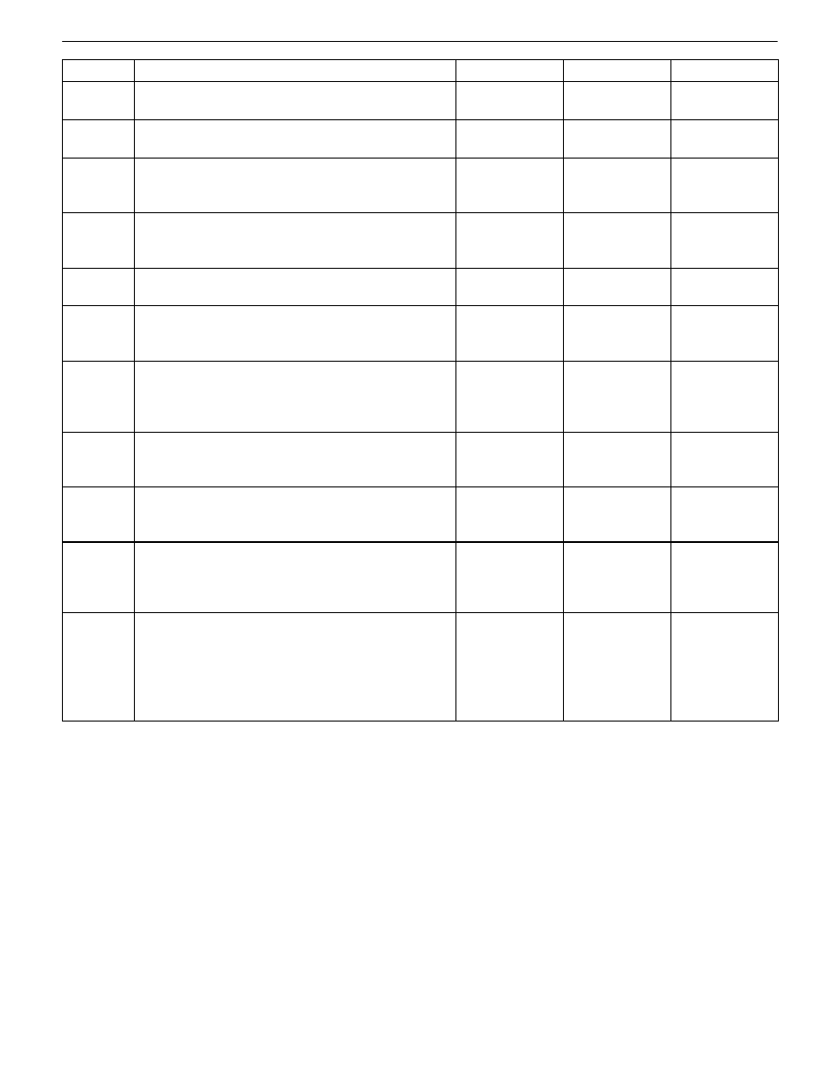
Step
No
Yes
Value(s)
Action
12
Replace the PCM/ECM.
Is the repair complete?
Go to Step 22
13
Repair the short to voltage in the MIL control circuit.
Is the repair complete?
Go to Step 22
14
Check for an open or a poor connection in the MIL
control circuit and repair as necessary.
Is the repair necessary?
Go to Step 22
Go to Step 17
15
With a test light still connected to the ground, probe
the ignition feed terminal F16.
Does the test light illuminate?
Go to Step 18
Go to Step 19
16
Repair the open battery feed circuit.
Is the repair complete?
Go to Step 22
17
Check for an open ignition feed circuit or fuse to the
MIL and repair as necessary.
Is the repair necessary?
Go to Step 22
Go to Step 20
18
Check for a poor connection in the battery feed ter-
minal A4 or the ignition feed terminal F16 and repair
as necessary.
Is the repair necessary?
Go to Step 22
Go to Step 21
19
Repair the open in the ignition feed circuit from termi-
nal F16.
Is the repair complete?
Go to Step 22
20
Replace the instrument panel cluster. Refer to Sec-
tion 9E, Instrumentation/Driver Information.
Is the repair complete?
Go to Step 22
21
Check for a faulty PCM/ECM ground connection at
the engine block or PCM/ECM connector and repair
as necessary.
Is the repair necessary?
Go to Step 22
Go to Step 12
22
1. Allow the engine to idle until normal operating
temperature is reached.
2. Check if any Diagnostic Trouble Codes (DTCs)
are set.
Are any DTCs displayed that have not been diag-
nosed?
Go to the appli-
cable DTC
table
System OK