Citroen C5 (2017 year). Manual - part 15
8
In the event of a breakdown
223
C5_en_Chap08_en-cas-de-panne_ed01-2016
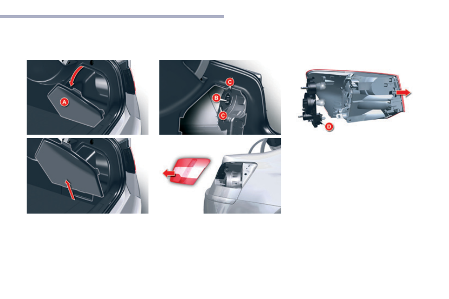
Wing-mounted lamps
F
Remove the lateral boot trim flap A. To do
so, pull it towards the inside of the boot,
then pull it upwards.
F Disconnect connector B
.
F
Unscrew the 2 fixings C.
F
Remove the lamp from its housing.
F Detach the bulb holder D
.
F
Replace the failed bulb.
F Refit the bulb holder D
.
F
Place the lamp in its housing.
F
Screw in the 2 fixings C.
F Refit connector B
.
F
Refit the side boot trim A.
For vehicles fitted with a Hi-Fi amplifier, on the
right-hand side slacken the screw by a quarter
turn, then pull the boot side trim A up.
You can use the wheelbrace to screw or
unscrew the fixings C.