Citroen C6 Dag (2008 year). Manual - part 10
148
VI
A
A
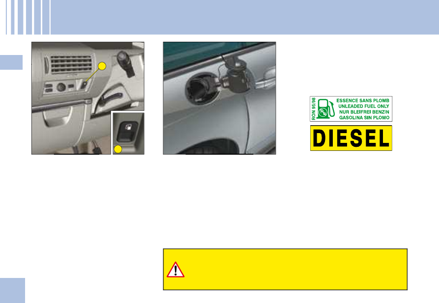
F U E L
If you should put in fuel that is not suitable for your vehicle's
engine type, it is imperative to have the tank drained before
you start the engine again.
While you are refuelling, the
engine must be stopped and the
ignition switched off.
For a petrol engine with a cata-
lytic converter, unleaded fuel is
compulsory.
The fi ller neck is narrower to
ensure that only unleaded petrol
can be put in.
When you are seeking to fi ll your
tank, do not persist after the
third cut-off; that could cause
your vehicle to malfunction.
To open the fl ap, press button A.
Undo the cap and attach it to the
tab on the inside of the fl ap.
Note:
The fuel fl ap is locked when
you lock your vehicle with the
remote control.
FUEL QUALITY
A label inside the fi ller fl ap tells you
which type of fuel to use.
The petrol engines are designed to
run on RON 95.
However, for better perform-
ance (petrol engine), we recom-
mend RON 98