Dodge Charger SRT (2019 year). Instruction - part 6


  Index      Dodge     Dodge Charger SRT (2019 year) - instruction in english


Search            copyright infringement  


Content      ..     4      5      6      7     ..


Dodge Charger SRT (2019 year). Instruction - part 6


NOTE:

HomeLink is disabled when the Vehicle Security

Alarm is active.

Before You Begin Programming HomeLink

Be sure that your vehicle is parked outside of the garage
before you begin programming.

For more efficient programming and accurate transmission
of the radio-frequency signal it is recommended that a new
battery be placed in the hand-held transmitter of the device
that is being programmed to the HomeLink system.

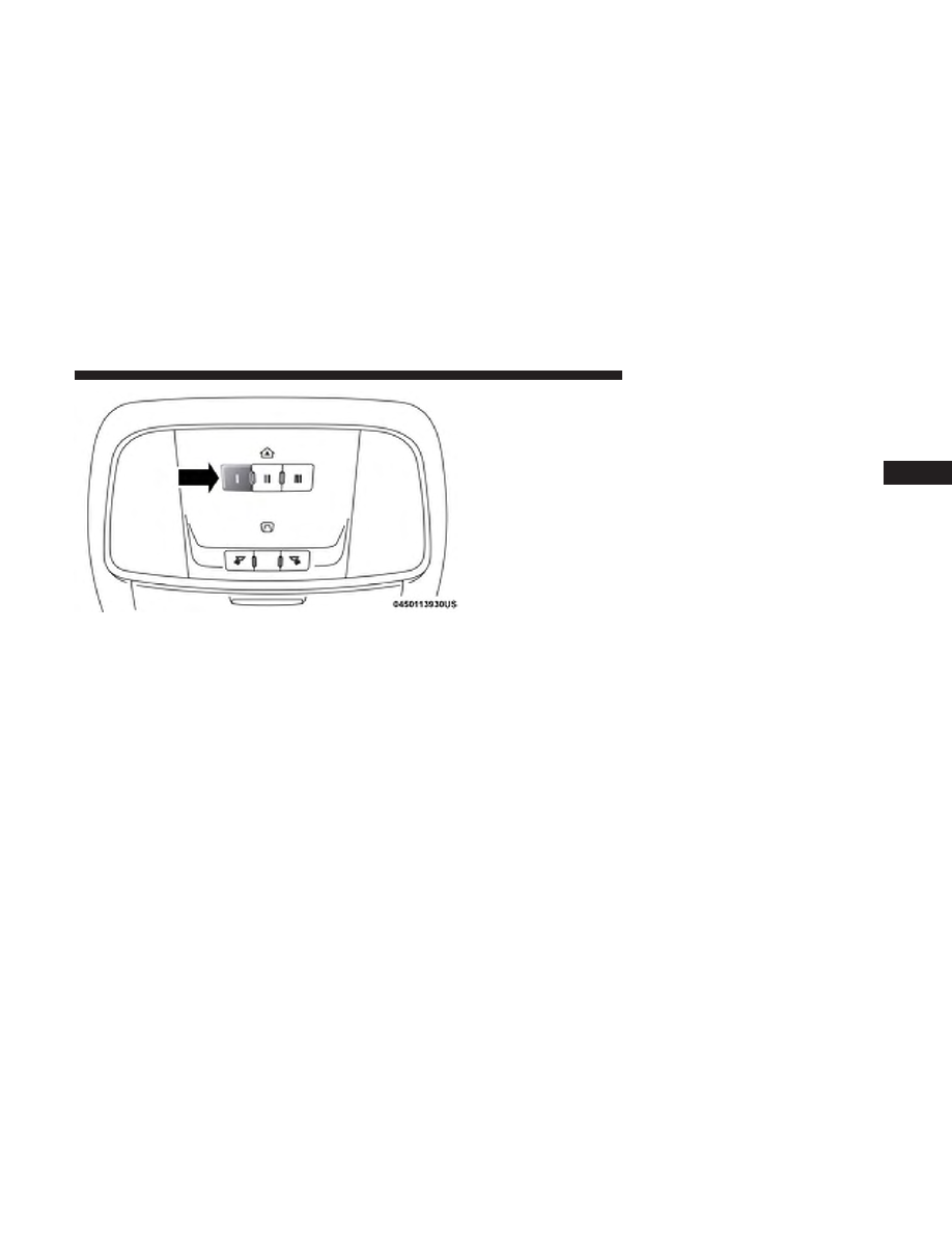
To erase the channels, place the ignition in the ON/RUN
position, and push and hold the two outside HomeLink
buttons (I and III) for up to 20 seconds or until the orange
indicator flashes.

NOTE:
• Erasing all channels should only be performed when

programming HomeLink for the first time. Do not erase
channels when programming additional buttons.

• If you have any problems, or require assistance, please

call toll-free 1-800-355-3515 or, on the Internet at
HomeLink.com for information or assistance.

Programming A Rolling Code

For programming garage door openers that were manufac-
tured after 1995. These garage door openers can be identi-
fied by the “LEARN” or “TRAIN” button located where
the hanging antenna is attached to the garage door opener.

NOTE:

It is NOT the button that is normally used to open

and close the door. The name and color of the button may
vary by manufacturer.

Overhead Console HomeLink Buttons

3

GETTING TO KNOW YOUR VEHICLE

93

1. Place the ignition in the ON/RUN position.

2. Place the hand-held transmitter 1 to 3 inches (3 to 8 cm)

away from the HomeLink button you wish to program
while keeping the HomeLink indicator light in view.

3. Push and hold the HomeLink button you want to

program while you push and hold the hand-held trans-
mitter button.

4. Continue to hold both buttons and observe the indicator

light. The HomeLink indicator will flash slowly and
then rapidly after HomeLink has received the frequency
signal from the hand-held transmitter. Release both
buttons after the indicator light changes from slow to
rapid.

5. At the garage door opener motor (in the garage), locate

the “LEARN” or “TRAINING” button. This can usually
be found where the hanging antenna wire is attached to
the garage door opener/device motor. Firmly push and
release the “LEARN” or “TRAINING” button. On some
garage door openers/devices there may be a light that
blinks when the garage door opener/device is in the
LEARN/TRAIN mode.

NOTE:

You have 30 seconds in which to initiate the next

step after the LEARN button has been pushed.

6. Return to the vehicle and push the programmed

HomeLink button twice (holding the button for two
seconds each time). If the garage door opener/device
activates, programming is complete.

NOTE:

If the garage door opener/device does not activate,

push the button a third time (for two seconds) to complete
the training.

Training The Garage Door Opener

1 — Door Opener
2 — Training Button

94

GETTING TO KNOW YOUR VEHICLE

To program the remaining two HomeLink buttons, repeat
each step for each remaining button. DO NOT erase the
channels.

Reprogramming A Single HomeLink Button (Rolling
Code)

To reprogram a channel that has been previously trained,
follow these steps:

1. Cycle the ignition to the ON/RUN position.

2. Push and hold the desired HomeLink button until the

indicator light begins to flash after 20 seconds. Do not
release the button.

3. Without releasing the button proceed with “Program-

ming A Rolling Code” step 2 and follow all remaining
steps.

Programming A Non-Rolling Code

For programming Garage Door Openers manufactured
before 1995.

1. Cycle the ignition to the ON/RUN position.

2. Place the hand-held transmitter 1 to 3 inches (3 to 8 cm)

away from the HomeLink button you wish to program
while keeping the HomeLink indicator light in view.

3. Press and hold the HomeLink button you want to

program while you press and hold the hand-held trans-
mitter button.

4. Continue to hold both buttons and observe the indicator

light. The HomeLink indicator will flash slowly and
then rapidly after HomeLink has received the frequency
signal from the hand-held transmitter. Release both
buttons after the indicator light changes from slow to
rapid.

5. Press and hold the programmed HomeLink button and

observe the indicator light.

• If the indicator light stays on constantly, programming

is complete and the garage door/device should acti-
vate when the HomeLink button is pressed.

• To program the two remaining HomeLink buttons,

repeat each step for each remaining button. DO NOT
erase the channels.

3

GETTING TO KNOW YOUR VEHICLE

95

Reprogramming A Single HomeLink Button
(Non-Rolling Code)

To reprogram a channel that has been previously trained,
follow these steps:

1. Cycle the ignition to the ON/RUN position.

2. Press and hold the desired HomeLink button until the

indicator light begins to flash after 20 seconds. Do not
release the button.

3. Without releasing the button, proceed with “Program-

ming A Non-Rolling Code” step 2 and follow all remain-
ing steps.

Canadian/Gate Operator Programming

For programming transmitters in Canada/United States
that require the transmitter signals to “time-out” after
several seconds of transmission.

Canadian radio frequency laws require transmitter signals
to time-out (or quit) after several seconds of transmission –
which may not be long enough for HomeLink to pick up
the signal during programming. Similar to this Canadian
law, some U.S. gate operators are designed to time-out in
the same manner.

It may be helpful to unplug the device during the cycling
process to prevent possible overheating of the garage door
or gate motor.

1. Cycle the ignition to the ON/RUN position.

2. Place the hand-held transmitter 1 to 3 inches (3 to 8 cm)

away from the HomeLink button you wish to program
while keeping the HomeLink indicator light in view.

3. Continue to press and hold the HomeLink button, while

you press and release (“cycle”) your hand-held trans-
mitter every two seconds until HomeLink has success-
fully accepted the frequency signal. The indicator light
will flash slowly and then rapidly when fully trained.

4. Watch for the HomeLink indicator to change flash rates.

When it changes, it is programmed. It may take up to 30
seconds or longer in rare cases. The garage door may
open and close while you are programming.

5. Press and hold the programmed HomeLink button and

observe the indicator light.

96

GETTING TO KNOW YOUR VEHICLE

NOTE:

• If the indicator light stays on constantly, programming

is complete and the garage door/device should acti-
vate when the HomeLink button is pressed.

• To program the two remaining HomeLink buttons,

repeat each step for each remaining button. DO NOT
erase the channels.

If you unplugged the garage door opener/device for
programming, plug it back in at this time.

Reprogramming A Single HomeLink Button (Canadian/
Gate Operator)

To reprogram a channel that has been previously trained,
follow these steps:

1. Cycle the ignition to the ON/RUN position.

2. Press and hold the desired HomeLink button until the

indicator light begins to flash after 20 seconds. Do not
release the button.

3. Without releasing the button, proceed with “Canadian/

Gate Operator Programming” step 2 and follow all
remaining steps.

Using HomeLink

To operate, push and release the programmed HomeLink
button. Activation will now occur for the programmed
device (i.e. garage door opener, gate operator, security
system, entry door lock, home/office lighting, etc.). The
hand-held transmitter of the device may also be used at
any time.

Security

It is advised to erase all channels before you sell or turn in
your vehicle.

To do this, push and hold the two outside buttons for 20
seconds until the orange indicator flashes. Note that all
channels will be erased. Individual channels cannot be
erased.

The HomeLink Universal Transceiver is disabled when the
Vehicle Security Alarm is active.

3

GETTING TO KNOW YOUR VEHICLE

97

Troubleshooting Tips

If you are having trouble programming HomeLink, here
are some of the most common solutions:
• Replace the battery in the Garage Door Opener hand-

held transmitter.

• Push the LEARN button on the Garage Door Opener to

complete the training for a Rolling Code.

• Did you unplug the device for programming and re-

member to plug it back in?

If you have any problems, or require assistance, please call
toll-free

1-800-355-3515

or,

on

the

Internet

at

HomeLink.com for information or assistance.

WARNING!

• Vehicle exhaust contains carbon monoxide, a danger-

ous gas. Do not run your vehicle in the garage while
programming the transceiver. Exhaust gas can cause
serious injury or death.

• Your motorized door or gate will open and close while

you are programming the universal transceiver. Do not
program the transceiver if people, pets or other objects

(Continued)

WARNING! (Continued)

are in the path of the door or gate. Only use this
transceiver with a garage door opener that has a “stop
and reverse” feature as required by Federal safety
standards. This includes most garage door opener mod-
els manufactured after 1982. Do not use a garage door
opener without these safety features. Call toll-free
1-800-355-3515 or, on the Internet at HomeLink.com 
for
safety information or assistance.

General Information

The following regulatory statement applies to all Radio
Frequency (RF) devices equipped in this vehicle:

This device complies with Part 15 of the FCC Rules and
with Innovation, Science and Economic Development
Canada license-exempt RSS standard(s). Operation is sub-
ject to the following two conditions:

1. This device may not cause harmful interference, and

2. This device must accept any interference received, in-

cluding interference that may cause undesired opera-
tion.

98

GETTING TO KNOW YOUR VEHICLE

NOTE:

Changes or modifications not expressly approved

by the party responsible for compliance could void the
user’s authority to operate the equipment.

INTERNAL EQUIPMENT

Storage

Glove Compartment

The glove compartment is located on the passenger side of
the instrument panel.

To open the glove compartment, pull the release handle.

Console Features

There is an open cubby bin located forward of the gear
selector.

Two separate storage compartments are also located un-
derneath the center console armrest.

Inside the center console armrest, there is a removable
upper storage tray that can be slid forward/rearward on
rails for access to the lower storage area. This tray has an
integrated coin holder, along with additional area for small
items and handheld devices. Below the upper tray, the

Glove Compartment

Center Console

3

GETTING TO KNOW YOUR VEHICLE

99

lower storage compartment is made for larger items, like
tissue boxes. In addition, the 12 volt power outlet, USB and
Aux jack are located here.

WARNING!

Do not operate this vehicle with a console compart-
ment lid in the open position. Driving with the console
compartment lid open may result in injury in a colli-
sion.

Door Storage

The door panels contain storage areas.

Upper Storage Tray

Front Door Trim Storage

100

GETTING TO KNOW YOUR VEHICLE

Cupholders

The cupholders are located in the forward edge of the
center console.

NOTE:

Hellcat models are not equipped with a rear seat

armrest.

Retractable Cover

Front Cupholders

3

GETTING TO KNOW YOUR VEHICLE

101

If equipped, the rear seat cupholders are located in the
center armrest between the rear seats. The cupholders are
positioned forward in the armrest and side-by-side to
provide convenient access to beverage cans or bottles while
maintaining a resting place for the rear occupant’s elbows.

Lighted Cupholders — If Equipped

On some vehicles the rear cupholders are equipped with a
light ring that illuminates the cupholders for the rear
passengers. The light ring is controlled by the Dimmer
Control. Refer to “Interior Lights” in “Getting To Know
Your Vehicle” for further information.

Electrical Power Outlets

Your vehicle is equipped with one 12 Volt (13 Amp) power
outlet on the instrument panel and one 12 Volt (13 Amp)
power outlet in the center console that can be used to power
cellular phones, small electronics and other low powered
electrical accessories. The power outlets are labeled with either
a “key” or a “battery” symbol to indicate how the outlet is
powered. Power outlets labeled with a “key” are powered
when the ignition switch is in the ON or ACC position, while
the outlets labeled with a “battery” are connected directly to
the battery and powered at all times.

Rear Seat Cupholders

Light Ring In Rear Cupholder

102

GETTING TO KNOW YOUR VEHICLE

NOTE:
• All accessories connected to the “battery” powered

outlets should be removed or turned off when the
vehicle is not in use to protect the battery against
discharge.

The front power outlet is located inside the storage area on
the center stack of the instrument panel.

WARNING!

Do not place ashes inside the cubby bin located on the
center console on vehicles not equipped with the ash
receiver tray. A fire leading to bodily injury could
result.

In addition to the front power outlet, there is also a power
outlet located in the storage area of the center console.

Front Power Outlet

Center Console Power Outlet

3

GETTING TO KNOW YOUR VEHICLE

103

NOTE:

If the Media Hub is in use, do not exceed the

maximum power of 100 Watts (8 Amps) for the center
console power outlet. When the Media Hub is not in use,
the outlet can deliver up to 160 Watts (13 Amps). If the
power rating is exceeded, the fuse protecting the system
needs to be replaced.

NOTE:

The instrument panel power outlet and dual rear

console USB ports can be changed to “battery” powered all
the time by moving the #12 20 Amp fuse from “IGN” to
“B+”. Refer to “Fuses” in “In Case Of Emergency” for
further information.

WARNING!

To avoid serious injury or death:
• Only devices designed for use in this type of outlet

should be inserted into any 12 Volt outlet.

• Do not touch with wet hands.

• Close the lid when not in use and while driving the

vehicle.

• If this outlet is mishandled, it may cause an electric

shock and failure.

CAUTION!

• Many accessories that can be plugged in draw power from

the vehicle’s battery even when not in use (i.e., cellular
phones, etc.). Eventually, if plugged in long enough, the
vehicle’s battery will discharge sufficiently to degrade
battery life and/or prevent the engine from starting.

(Continued)

Power Outlet Fuse Locations

1 — #12 Fuse 20 Amp Yellow Instrument Panel Power Outlet/Dual
USB Charge Only Ports
2 — #38 Fuse 20 Amp Yellow Center Console Power Outlet/Media
Hub

104

GETTING TO KNOW YOUR VEHICLE

CAUTION! (Continued)

• Accessories that draw higher power (i.e., coolers,

vacuum cleaners, lights, etc.) will degrade the battery
even more quickly. Only use these intermittently and
with greater caution.

• After the use of high power draw accessories or long

periods of the vehicle not being started (with acces-
sories still plugged in), the vehicle must be driven a
sufficient length of time to allow the alternator to
recharge the vehicle’s battery.

• Power outlets are designed for accessory plugs only.

Do not hang any type of accessory or accessory
bracket from the plug. Improper use of the power
outlet can cause damage.

Wireless Charging Pad — If Equipped

Your vehicle may be equipped with an Open Dots compat-
ible wire-free phone charging surface located in the center
console. The wireless charger features continuous wireless
charging during vehicle operation and allows for uninter-
rupted Bluetooth streaming to properly equipped vehicle
audio systems.

In order to enjoy the convenience of Open Dots wire-free
charging, you must obtain an aftermarket wireless-enabled
case and then install the case on your phone. Set the phone
on the wireless charging pad face up. The charging indi-
cator on your phone will light up indicating that your
phone is charging.

NOTE:

The charging pad is safe to the touch. However, if

metallic items are placed on the charging surface while in
use, the device will turn off. Clean all spills immediately
and allow to dry before using.

Wireless Charging Pad

3

GETTING TO KNOW YOUR VEHICLE

105

For phones that already have built-in wireless charging
capability (Samsung, Apple iPhone 8, 8 Plus and X
Phones), a Qi Adapter is available to charge your phone
using the Open Dot wire-free phone charging surface.
Simply place the Qi Adapter (dot side down) on the
charging surface and then place your built-in charging
capable phone face up on top of the Qi Adapter. This
product may not be compatible with all vehicle/Open Dots
compatible wire-free phone charging surface combina-
tions.

CAUTION!

The key fob should not be placed on the charging pad
or within 15 cm (150 mm) of it. Doing so can cause
excessive heat buildup and damage to the fob. Placing
the fob in close proximity of the charging pad blocks
the fob from being detected by the vehicle and pre-
vents the vehicle from starting.

To get your free aftermarket phone case or Qi Adapter, go
to http://invehiclewirelesscharging.com. You will need
your vehicle/voucher identification number (located in
your vehicle’s glove box). If you have any questions or are
not sure if you need a phone case or the Qi Adapter, please
call our customer support line for assistance: 877–360–7702

Sunglasses Bin Door

At the front of the console a compartment is provided for
the storage of a pair of sunglasses. The storage compart-
ment access is a “push/push” design. Push the chrome pad
on the door to open. Push the chrome pad on the door to
close.

Sunglasses Bin Door

106

GETTING TO KNOW YOUR VEHICLE

GETTING TO KNOW YOUR INSTRUMENT PANEL

CONTENTS

䡵 INSTRUMENT CLUSTER . . . . . . . . . . . . . . . . . .108

▫ Instrument Cluster Descriptions . . . . . . . . . . . .108

䡵 INSTRUMENT CLUSTER DISPLAY . . . . . . . . . . .110

▫ Location And Controls . . . . . . . . . . . . . . . . . . .110
▫ Engine Oil Life Reset . . . . . . . . . . . . . . . . . . . .112
▫ Performance Shift Indicator (PSI) —

If Equipped . . . . . . . . . . . . . . . . . . . . . . . . . . .113

▫ Instrument Cluster Display Selectable Menu

Items . . . . . . . . . . . . . . . . . . . . . . . . . . . . . . .113

▫ Battery Saver On/Battery Saver Mode Message —

Electrical Load Reduction Actions —
If Equipped . . . . . . . . . . . . . . . . . . . . . . . . . .120

䡵 WARNING LIGHTS AND MESSAGES . . . . . . . . .122

▫ Red Warning Lights . . . . . . . . . . . . . . . . . . . . .122
▫ Yellow Warning Lights . . . . . . . . . . . . . . . . . . .126
▫ Yellow Indicator Lights. . . . . . . . . . . . . . . . . . .131
▫ Green Indicator Lights . . . . . . . . . . . . . . . . . . .131
▫ White Indicator Lights . . . . . . . . . . . . . . . . . . .132
▫ Blue Indicator Lights . . . . . . . . . . . . . . . . . . . .133

䡵 ONBOARD DIAGNOSTIC SYSTEM — OBD II . . .133

▫ Onboard Diagnostic System (OBD II)

Cybersecurity . . . . . . . . . . . . . . . . . . . . . . . . .134

䡵 EMISSIONS INSPECTION AND MAINTENANCE

PROGRAMS . . . . . . . . . . . . . . . . . . . . . . . . . . .135

4

INSTRUMENT CLUSTER

Instrument Cluster Descriptions

1. Tachometer

• Indicates the engine speed in revolutions per minute

(RPM x 1000).

2. Instrument Cluster Display

• When the appropriate conditions exist, this display

shows the instrument cluster display messages. Refer
to “Instrument Cluster Display” in “Getting To Know
Your Instrument Panel” for further information.

Instrument Cluster For SRT 6.2L Supercharged Engine

108

GETTING TO KNOW YOUR INSTRUMENT PANEL


Content      ..     4      5      6      7     ..