Dodge 1500 (2012 year). Instruction - part 15


  Index      Dodge     Dodge 1500 (2012 year) - instruction in english


Search            copyright infringement  


Content      ..     13      14      15      16     ..


Dodge 1500 (2012 year). Instruction - part 15


Bed Rail Tie-Down System

CAUTION!

The maximum load per cleat should not exceed
250 lbs (113 kg) and the angle of the load on each cleat
should not exceed 45 degrees above horizontal, or
damage to the cleat or cleat rail may occur.

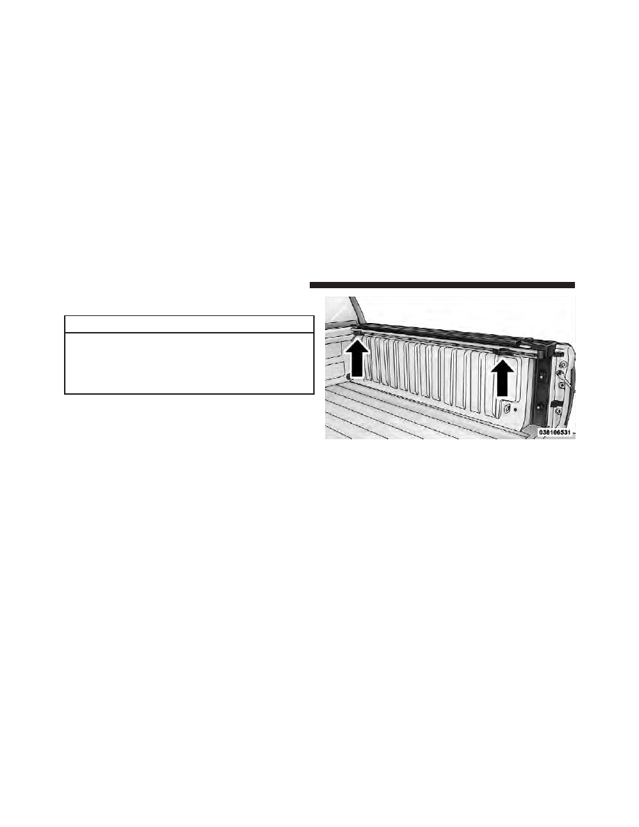
There are two adjustable cleats on each side of the bed
that can be used to assist in securing cargo.

Each cleat must be located and tightened down in one of
the detents, along either rail, in order to keep cargo
properly secure.

Adjustable Cleats

236

UNDERSTANDING THE FEATURES OF YOUR VEHICLE

To move the cleat to any position on the rail, turn the nut
counterclockwise, approximately three turns. Then pull
out on the cleat and slide it to the detent nearest the
desired location. Make sure the cleat is seated in the
detent and tighten the nut.

To remove the cleats from the utility rail, remove the end
cap by pushing up on the locking tab, located on the
bottom of the end cap. Slide the cleat off the end of the
rail.

1 — Utility Rail Detent
2 — Cleat Retainer Nut
3 — Utility Rail Cleat

Utility Rail End Cap

3

UNDERSTANDING THE FEATURES OF YOUR VEHICLE

237

SLIDE-IN CAMPERS

Camper Applications

Certain truck models are not recommended for slide-in
campers. To determine if your vehicle is excluded, please
refer to the “Consumer Information Truck-Camper Load-
ing” document available from your authorized dealer.
For safety reasons, follow all instructions in this impor-
tant document.

NOTE:

When a cap or pickup camper is installed on a

vehicle, an alternate Center High-Mounted Stop Light
(CHMSL) must be provided.

EASY-OFF TAILGATE

To simplify mounting of a camper unit with an overhang,
the tailgate can be removed.

NOTE:

If your vehicle is equipped with a rear camera

the electrical connector must be disconnected prior to
removing the tailgate.

Disconnecting the Rear Camera — If Equipped

1. Open the tailgate to access the rear camera connector
bracket located on the rear sill.

2. Remove the connector bracket from the sill by press-
ing inward in the locking tab.

Connector Bracket

238

UNDERSTANDING THE FEATURES OF YOUR VEHICLE

3. Disconnect the chassis wiring harness, ensuring the
connector bracket does not fall into the sill.

4. Connect the chassis plug and bracket (provided in the
glove box) to the chassis wiring harness and insert the
bracket back into the sill.

5. Connect the tailgate plug (provided in the glove box)
to the tailgate wiring harness to ensure that the terminals
do not corrode.

6. Tape the tailgate harness and bracket against the
forward-facing surface of the tailgate. This will prevent
damaging the connector and bracket when storing or
reinstalling the tailgate.

Removing The Tailgate

1. Disconnect the wiring harness for the rear camera (if
equipped), refer to “Disconnecting the Rear Camera — If
Equipped” in this section.

2. Unlatch the tailgate and remove the support cables by
releasing the lock tang from the pivot.

Locking Tab

3

UNDERSTANDING THE FEATURES OF YOUR VEHICLE

239

NOTE:

Make sure tailgate is supported when removing

support cables.

3. Raise the tailgate to a 45 degree angle.

4. Raise the right side of the tailgate until the right side
pivot clears the hanger bracket.

5. Slide the entire tailgate to the right to free the left side
pivot.

6. Remove the tailgate from the vehicle.

NOTE:

Do not carry the tailgate loose in the truck

pickup box.

WARNING!

To avoid inhaling carbon monoxide, which is deadly,
the exhaust system on vehicles equipped with “Cap
or Slide-In Campers” should extend beyond the
overhanging camper compartment and be free of
leaks.

Locking Tailgate

The lock is located next to the tailgate handle. The
tailgate can be locked using the vehicle key.

Locking Tang

240

UNDERSTANDING THE FEATURES OF YOUR VEHICLE

UNDERSTANDING YOUR INSTRUMENT PANEL

CONTENTS

䡵 Instrument Panel Features . . . . . . . . . . . . . . . 245
䡵 Switch Bank Button Description . . . . . . . . . . . 246

▫ Upper Switch Bank . . . . . . . . . . . . . . . . . . . 246
▫ Lower Switch Bank . . . . . . . . . . . . . . . . . . . 246

䡵 Instrument Cluster — Base . . . . . . . . . . . . . . . 248
䡵 Instrument Cluster — Premium . . . . . . . . . . . 249
䡵 Instrument Cluster Descriptions . . . . . . . . . . . 250

䡵 Electronic Vehicle Information Center

(EVIC) — If Equipped . . . . . . . . . . . . . . . . . . . 268

▫ EVIC Displays . . . . . . . . . . . . . . . . . . . . . . 269
▫ Fuel Economy / Fuel Saver Mode / Distance

To Empty (DTE) — If Equipped . . . . . . . . . . 276

▫ Trip Functions . . . . . . . . . . . . . . . . . . . . . . 277
▫ Vehicle Info

(Customer Information Features) . . . . . . . . . 278

▫ Tire PSI . . . . . . . . . . . . . . . . . . . . . . . . . . . 279
▫ Units . . . . . . . . . . . . . . . . . . . . . . . . . . . . . 279

4

▫ Compass / Temperature Display . . . . . . . . . 280
▫ Customer-Programmable Features

(System Setup) . . . . . . . . . . . . . . . . . . . . . . 282

䡵 Media Center 730N/430/430N (RHR/RER/

RBZ/RHB) CD/DVD/HDD/NAV — If
Equipped 
. . . . . . . . . . . . . . . . . . . . . . . . . . . . 288

▫ Operating Instructions (Voice Command

System) — If Equipped . . . . . . . . . . . . . . . . 289

▫ Operating Instructions

(Uconnect™ Phone) — If Equipped . . . . . . . 289

䡵 Media Center 130 (Sales Code RES) . . . . . . . . . 289

▫ Operating Instructions — Radio Mode . . . . . 289
▫ Operation Instructions — CD Mode For CD

And MP3 Audio Play . . . . . . . . . . . . . . . . . 292

▫ Notes On Playing MP3 Files . . . . . . . . . . . . 294

▫ Operation Instructions - Auxiliary Mode . . . . 297

䡵 Media Center 130 With Satellite Radio

(Sales Code RES+RSC). . . . . . . . . . . . . . . . . . . 298

▫ Operating Instructions — Radio Mode . . . . . 298
▫ Operation Instructions — CD Mode For CD

And MP3 Audio Play . . . . . . . . . . . . . . . . . 304

▫ Notes On Playing MP3 Files . . . . . . . . . . . . 306
▫ List Button (CD Mode For MP3 Play) . . . . . . 308
▫ Info Button (CD Mode For MP3 Play) . . . . . . 308
▫ Uconnect™ Multimedia (Satellite Radio) — If

Equipped . . . . . . . . . . . . . . . . . . . . . . . . . . 309

▫ Operating Instructions (Uconnect™ Phone)

— If Equipped . . . . . . . . . . . . . . . . . . . . . . 313

242

UNDERSTANDING YOUR INSTRUMENT PANEL

䡵 iPod威/USB/MP3 Control — If Equipped . . . . . 313

▫ Connecting The iPod威 Or External USB

Device . . . . . . . . . . . . . . . . . . . . . . . . . . . . 314

▫ Using This Feature . . . . . . . . . . . . . . . . . . . 315
▫ Controlling The iPod威 Or External USB

Device Using Radio Buttons . . . . . . . . . . . . . 315

▫ Play Mode . . . . . . . . . . . . . . . . . . . . . . . . . 316
▫ List Or Browse Mode . . . . . . . . . . . . . . . . . 317
▫ Bluetooth Streaming Audio (BTSA) . . . . . . . . 319

䡵 Uconnect™ Multimedia Video Entertainment

System (VES)™ — If Equipped . . . . . . . . . . . . 320

▫ Getting Started . . . . . . . . . . . . . . . . . . . . . . 320
▫ Single Video Screen . . . . . . . . . . . . . . . . . . . 321
▫ Play Video Games . . . . . . . . . . . . . . . . . . . . 324

▫ Listen To An Audio Source On Channel 2

While A Video Is Playing On Channel 1 . . . . 327

▫ Important Notes For Single Video Screen

System . . . . . . . . . . . . . . . . . . . . . . . . . . . . 329

▫ Play A DVD Using The

Touch-Screen Radio . . . . . . . . . . . . . . . . . . . 329

▫ Remote Control . . . . . . . . . . . . . . . . . . . . . 332
▫ Remote Control Storage . . . . . . . . . . . . . . . . 334
▫ Locking The Remote Control . . . . . . . . . . . . 335
▫ Replacing The Batteries . . . . . . . . . . . . . . . . 335
▫ Headphones Operation . . . . . . . . . . . . . . . . 336
▫ Controls . . . . . . . . . . . . . . . . . . . . . . . . . . . 337
▫ Replacing The Batteries . . . . . . . . . . . . . . . . 338

4

UNDERSTANDING YOUR INSTRUMENT PANEL

243

▫ Unwired威 Stereo Headphone Lifetime

Limited Warranty . . . . . . . . . . . . . . . . . . . . 338

▫ System Information . . . . . . . . . . . . . . . . . . . 339

䡵 Steering Wheel Audio

Controls — If Equipped. . . . . . . . . . . . . . . . . . 353

▫ Radio Operation . . . . . . . . . . . . . . . . . . . . . 354
▫ CD Player . . . . . . . . . . . . . . . . . . . . . . . . . 354

䡵 CD/DVD Disc Maintenance . . . . . . . . . . . . . . 354
䡵 Radio Operation And Mobile Phones . . . . . . . 355

䡵 Climate Controls . . . . . . . . . . . . . . . . . . . . . . 355

▫ Instruction Heating And Air Conditioning

System . . . . . . . . . . . . . . . . . . . . . . . . . . . . 356

▫ Automatic Temperature Control (ATC) — If

Equipped . . . . . . . . . . . . . . . . . . . . . . . . . . 360

▫ Summer Operation . . . . . . . . . . . . . . . . . . . 365
▫ Winter Operation . . . . . . . . . . . . . . . . . . . . 365
▫ Vacation/Storage . . . . . . . . . . . . . . . . . . . . 366
▫ Window Fogging And Frosting . . . . . . . . . . 366
▫ Outside Air Intake . . . . . . . . . . . . . . . . . . . 366
▫ Operating Tips . . . . . . . . . . . . . . . . . . . . . . 367

244

UNDERSTANDING YOUR INSTRUMENT PANEL

INSTRUMENT PANEL FEATURES

1 — Headlight Switch

7 — 115v Power Inverter Outlet

13 — Transfer Case Position Switch

2 — Instrument Cluster

8 — Power Outlet

14 — Ignition Switch

3 — Radio

9 — Lower Switch Bank

15 — Hood Release

4 — Upper Switch Bank

10 — Cup Holders

16 — Parking Brake Release

5 — Upper Glove Compartment

11 — Climate Controls

6 — Lower Glove Compartment

12 — Power Outlet/Cigar Lighter

4

UNDERSTANDING YOUR INSTRUMENT PANEL

245

SWITCH BANK BUTTON DESCRIPTION

Upper Switch Bank

The upper switch bank is located on the center of the
instrument panel.

1. TOW/HAUL
Refer to “Starting And Operating” for more information.

2. ESC OFF
Refer to “Starting And Operating” for more information.

3. HAZARD WARNING FLASHER
Refer to “What To Do In Emergencies” for more infor-
mation.

4. 115V POWER INVERTER
Refer to “Understanding The Features Of Your Vehicle”
for more information.

5. REAR PARK ASSIST
Refer to “Understanding The Features Of Your Vehicle”
for more information.

6. TPMS LIGHT LOAD — IF EQUIPPED
Refer to “Starting And Operating” for more information.

Lower Switch Bank

The lower switch bank is located on the center of the
instrument panel.

246

UNDERSTANDING YOUR INSTRUMENT PANEL

1. HEATED SEATS
Refer to “Understanding The Features Of Your Vehicle”
for more information.

2. VENTILATED SEATS
Refer to “Understanding The Features Of Your Vehicle”
for more information.

3. HEATED STEERING WHEEL
Refer to “Understanding The Features Of Your Vehicle”
for more information.

4

UNDERSTANDING YOUR INSTRUMENT PANEL

247

INSTRUMENT CLUSTER — BASE

248

UNDERSTANDING YOUR INSTRUMENT PANEL

INSTRUMENT CLUSTER — PREMIUM

4

UNDERSTANDING YOUR INSTRUMENT PANEL

249

INSTRUMENT CLUSTER DESCRIPTIONS

1. Tachometer
The tachometer indicates engine speed in Revolutions
Per Minute (RPM x 1000).

CAUTION!

Do not operate the engine with the tachometer
pointer at high RPM for extended periods. Engine
damage may occur.

2. Turn Signal Indicators

The arrow will flash with the exterior turn signal
when the turn signal lever is operated.

NOTE:

• A continuous chime will sound if the vehicle is driven

more than 1 mile (1.6 km) with either turn signal on.

• Check for an inoperative outside light bulb if either

indicator remains on and does not flash, or flashes at a
rapid rate.

3. Fuel Gauge
Shows level of fuel in tank when ignition switch is in the
ON/RUN position.

4. Temperature Gauge
The temperature gauge shows engine coolant tempera-
ture. Any reading within the normal range indicates that
the engine cooling system is operating satisfactorily.

The gauge pointer will likely indicate a higher tempera-
ture when driving in hot weather, up mountain grades,
or when towing a trailer. It should not be allowed to
exceed the upper limits of the normal operating range.

250

UNDERSTANDING YOUR INSTRUMENT PANEL

CAUTION!

Driving with a hot engine cooling system could
damage your vehicle. If the temperature gauge reads
“H” pull over and stop the vehicle. Idle the vehicle
with the air conditioner turned off until the pointer
drops back into the normal range. If the pointer
remains on the “H” and you hear continuous chimes,
turn the engine off immediately and call an autho-
rized dealership for service.

WARNING!

A hot engine cooling system is dangerous. You or
others could be badly burned by steam or boiling
coolant. You may want to call an authorized dealer-
ship for service if your vehicle overheats. If you
decide to look under the hood yourself, see “Main-
taining Your Vehicle”. Follow the warnings under the
Cooling System Pressure Cap paragraph.

5. Speedometer
The speedometer shows the vehicle speed in miles per
hour and/or kilometers per hour (mph/km/h).

6. 4 LOW

This light alerts the driver that the vehicle is in
the four-wheel drive LOW mode. The front and
rear driveshafts are mechanically locked to-
gether forcing the front and rear wheels to

4

UNDERSTANDING YOUR INSTRUMENT PANEL

251


Content      ..     13      14      15      16     ..