Scania DC16 EMS with S6/PDE. Industrial engine. Instruction - part 2


  Index      Scania     Scania DC16 EMS with S6/PDE. Industrial engine. Instruction


Search            copyright infringement  


Content      ..      1      2      3      ..


Scania DC16 EMS with S6/PDE. Industrial engine. Instruction - part 2


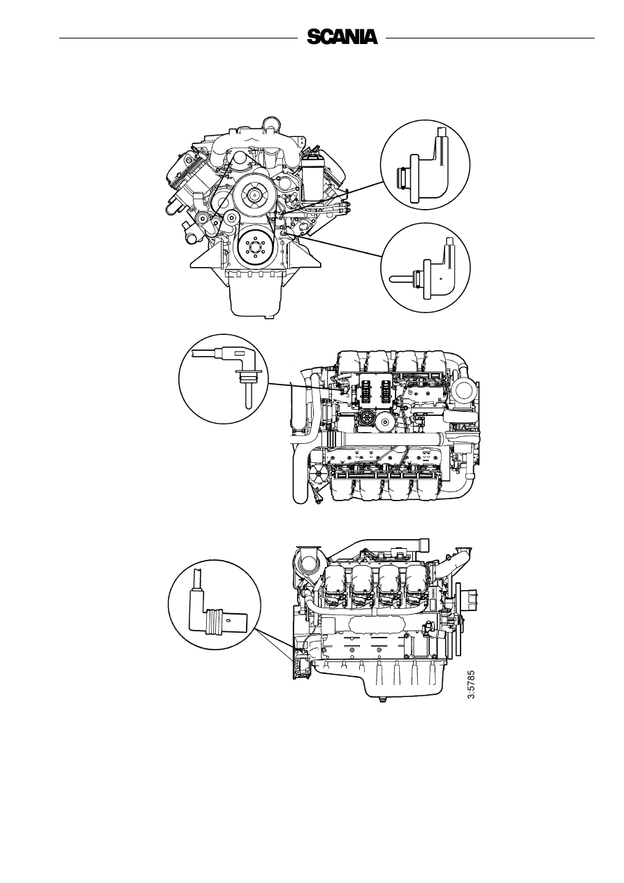
Positions of sensors for EMS with S6 on DC16

1.

Oil pressure sensor

2.

Coolant temperature sensor

3.

Charge air temperature and pressure sensor

4.

Engine speed sensor (2)

2

1

4

3

18

Troubleshooting using flash codes for the EMS 

control unit

• The diagnostics lamp on the instrument panel(s) always comes on for 

two seconds when the system is powered up.

• As soon as a fault is detected by the control unit, it is stored in the 

EEPROM fault code memory and the diagnostics lamp on the 

instrument panel(s) comes on.

• The diagnostic lamp will stay on for as long as a fault is active. Even if 

the lamp has gone off and the fault is no longer active, the code can 

generally be read off by following the instructions below.

Reading off control unit fault codes

1.

Turn on the ignition.

2.

Activate the diagnostics switch to the left to view the flash codes for the 

control unit (EMS).

3.

A fault code will then flash on the diagnostics lamp. This flash code 

consists of long flashes (approximately 1 second long) and short flashes 

(0.3 seconds long). Long flashes are equivalent to tens and short flashes 

to ones.

Example: long - short - short fault code 12.

4.

Repeat this procedure until the first flash code is repeated. This means 

that the entire fault code memory has been flashed out. If the fault code 

memory is empty, only one long flash approximately 4 seconds long 

will be given.

5.

See the flash code table on the next page for a description and to locate 

the fault.

6.

In order to obtain further information on the fault code, the PC-based 

diagnostics tool or Scania EMS Display must be used. Contact an 

authorised Scania workshop.

7.

When a fault has been rectified the fault code can be erased as described 

below.

Erasing fault codes

1.

Switch off the ignition. If dual instrumentation has been fitted, the 

ignition must be switched off on both panels.

2.

Activate the diagnostics switch in the same direction as the flash codes 

indicate, i.e. to the right for the coordinator (COO) or to the left for 

EMS. 

3.

Switch on the ignition and at the same time keep the diagnostics switch 

activated, to the right (COO) or to the left (EMS), for 3 seconds.

4.

This will erase passive fault codes which can be read via flash codes for 

the relevant system. The rest of the fault codes will remain in the 

EEPROM and can only be deleted using the PC tool.

Overview of flash codes for the EMS control unit 

Code

Description

Code

Description

0

No fault detected.

53

PDE in cylinder 3: The solenoid valve is not 

working properly.

11

Overrevving. One or both engine speed sensors are 

indicating speeds in excess of 3,000 rpm.

54

PDE in cylinder 4: The solenoid valve is not 

working properly.

12

Engine speed sensor 1 faulty, or incorrect signal.

55

PDE in cylinder 5: The solenoid valve is not 

working properly.

13

Rotation speed sensor 2 faulty, or incorrect signal.

56

PDE in cylinder 6: The solenoid valve is not 

working properly.

14

Coolant temperature sensor faulty, or incorrect 

signal.

57

PDE in cylinder 7: The solenoid valve is not 

working properly.

15

Charge air temperature sensor faulty, or incorrect 

signal.

58

PDE in cylinder 8: The solenoid valve is not 

working properly.

16

Charge air pressure sensor faulty, or incorrect 

signal.

59

Incorrect signal in extra analogue input.

17

Oil temperature sensor faulty, or incorrect signal.

61

Incorrect control unit shutdown.

18

Oil pressure sensor faulty, or incorrect signal.

66

Shutdown due to coolant level.

21

Coolant level sensor faulty.

68

Alternator charging incorrectly.

23

Internal fault code in the coordinator.

69

Starter motor function interrupted or not activated.

24

Accelerator/brake. If the accelerator and brake 

pedals have been operated simultaneously.

82

Rotation speed above ref.speed at start.

25

Accelerator pedal sensor/idling switch.

Accelerator pedal sensor/kickdown switch.

83

Fault in memory circuit (EEPROM) in control unit.

27

Engine shutdown bypassed.

84

Data transfer to the control unit memory 

(EEPROM) has been interrupted.

28

Shutdown due to oil pressure.

85

Incorrect internal temperature in the control unit.

31

Torque limitation due to oil pressure.

86

Internal fault in the control unit: Fault in hardware 

control.

32

Incorrect parameters for limp home function.

87

Fault in control unit RAM.

33

Battery voltage incorrect or no signal.

88

Internal control unit fault: Memory fault.

37

Emergency shutdown switch activated in 

accordance with CAN message from coordinator.

89

Defective seal: Prohibited changes in software.

43

CAN circuit faulty in the control unit.

93

Rotation speed sensors faulty or not connected.

47

Immobiliser function. Ignition key code incorrect.

94

Shutdown due to high coolant temperature.

48

CAN message from the coordinator incorrect or 

missing.

96

Torque limitation due to high coolant temperature.

49

Incorrect CAN version in control unit or 

coordinator.

98

Incorrect voltage supply to one of the sensors.

51

PDE in cylinder 1: The solenoid valve is not 

working properly.

99

Internal hardware fault in the processor (TPU).

52

PDE in cylinder 2: The solenoid valve is not 

working properly.

20

Troubleshooting using flash codes for the EMS 

coordinator

• The diagnostics lamp on the instrument panel(s) always comes on for 

two seconds when the system is powered up

• As soon as a fault is detected by the coordinator, it is stored in the 

EEPROM fault code memory and the diagnostics lamp on the 

instrument panel(s) comes on.

• Even if the lamp has gone off and the fault is no longer active, the code 

can generally be read off by following the instructions below.

Reading off coordinator fault codes

1.

Turn on the ignition.

2.

Activate the diagnostics switch to the right for 1 second to view the flash 

codes for the coordinator (COO). 

3.

A fault code will then flash on the diagnostics lamp. This flash code 

consists of long flashes (approximately 1 second long) and short flashes 

(0.3 seconds long). Long flashes are equivalent to tens and short flashes 

to ones.

Example: long - short - short fault code 12.

4.

Repeat this procedure until the first flash code is repeated. This means 

that the entire fault code memory has been flashed out. If the fault code 

memory is empty, only one long flash (approximately 4 seconds long) 

will be given.

5.

See the flash code table on the next page for a description and to locate 

the fault.

6.

In order to obtain further information about the fault code, the PC-based 

diagnostics tool or Scania EMS Display must be used. Contact an 

authorised Scania workshop. 

7.

When a fault has been rectified the fault code can be erased as described 

below.

Erasing fault codes

1.

Switch off the ignition. If dual instrumentation has been fitted, the 

ignition must be switched off on both panels.

2.

Activate the diagnostics switch in the same direction as the flash codes 

indicate, i.e. to the right for the coordinator (COO) or to the left for 

EMS. 

3.

Switch on the ignition and at the same time keep the diagnostics switch 

activated, to the right (COO) or to the left (EMS), for 3 seconds.

4.

This will erase passive fault codes which can be read via flash codes for 

the relevant system. The rest of the fault codes will remain in the 

EEPROM and can only be deleted using the PC tool.

Overview of flashing codes for coordinator

1) Single speed engine
2) All-speed engine

Flash code

Fault description

11

1)

Incorrect signal from the fine adjustment for the nominal engine speed signal.

11

2)

Incorrect signals from the accelerator pedal sensor.

12

1)

Incorrect signal from the resistor module for governor setting.

12

2)

Incorrect signal from the resistor module for idle and fixed speed setting.

13

No communication (EMS) with the engine. 

14

Short circuit in the tachometer signal cable.

15

Faulty atmospheric pressure sensor. 

17

Short-circuit in the coolant temperature gauge signal cable.

18

Short circuit in the oil pressure gauge signal cable.

19

Short circuit in the oil pressure lamp signal cable.

21

Different versions of the communications protocol in the coordinator and EMS. 

22

Faulty start switch or short circuit.

23

The supply voltage is too high.

24

The supply voltage is too low.

25

Check value from End of line (EOL) is incorrect.

26

Speed sensor signal missing or incorrect.

27

The signals from the RCB (Remote Control Box) switches are implausible. 

28

Incorrect signals from the droop setting switches.

29

Faulty remote start switch or short circuit.

31

No communication from the slave coordinator or the master coordinator. 

32

Short circuit in the signal cable to the coolant temperature warning lamp.

33

Short circuit in the signal cable to the charge warning lamp.

34

Incorrect signal from the Fixed speed switches. 

35

Fault in CAN communication.

22

Starting and running

First start

When the engine is started for the first time, carry out the maintenance points 

listed under "First start" in the maintenance schedule; see page 29.
Since the points are important for satisfactory operation of the engine right 

from the outset, they are also listed below.

1. Checking the oil level; see page 31.
6. Checking the coolant; see page 36.

The coolant must contain corrosion inhibitor to protect the cooling 
system from corrosion.

If there is a danger of freezing:

- Only antifreeze glycol should be used in the coolant as protection 

against corrosion. We recommend only nitrite-free antifreeze glycols 

with the following supplier designations:
BASF G48 or BASF D542

- The concentration of glycol should be 30-60% by volume depending on 

the ambient temperature. 30% glycol by volume provides anti-freeze 

protection down to -16°C. See page 37.

- Never top up with water alone or glycol alone! Fluid losses must 

always be replaced with pre-mixed coolant having the same glycol 

concentration as that in the engine. If the glycol content drops, both 

anti-freeze protection and protection against corrosion are impaired.

Note:

A glycol concentration below 30% by volume will not provide 

sufficient protection against corrosion. Glycol concentrations 

higher than 60% do not improve anti-freeze protection and have 

an adverse effect on engine cooling capacity.

If there is no danger of freezing:

- Only Scania Corrosion Inhibitor should be used in the coolant as 

protection against corrosion. The correct concentration of corrosion 

inhibitor is 8-12% by volume, and this must never drop below 8% by 

volume. The inhibitor in Scania Corrosion Inhibitoris free of nitrites.

- First filling: Fill up the system with water + 10% by volume Scania 

Corrosion Inhibitor. Use drinking water with a pH of 6-9.

- Never top up with water alone or corrosion inhibitor alone!

Fluid losses must always be replaced with ready-mixed 

coolant: water + 10% by volume Scania Corrosion Inhibitor.

Coolant filter (not standard equipment)

Only coolant filters without inhibitor may be used. The use of coolant filters 

increases the life of the coolant and reduces the risk of deposition corrosion.

Coolant composition:

If there is a danger of freezing:

min 30% glycol by volume

max 60% glycol by volume

If there is no danger of freezing:

8-12% by volume

Scania Corrosion Inhibitor

(no glycol)

The recommended glycols must 

not be mixed with glycol 

containing nitrite-based 

corrosion inhibitor. 

Ethylene glycol and corrosion 

inhibitor can be fatal if 

imbibed.

Avoid contact with the skin.

Overdosing with Scania 

Corrosion Inhibitor and mixing 

with glycol can cause sludge to 

be formed.

If a coolant filter has been fitted 

it must not contain inhibitor.

Important

!

Important

!

Important

!

Important

!

12. Checking the fuel level; see page 44.
14. Checking the electrolyte level in batteries; see page 46.
15. Checking the state of charge in batteries; see page 46.
18. Checking the drive belt tension; see page 48.

Checks before running

Before running, "Daily maintenance" as described in the maintenance 

schedule should be carried out; see page 29.

Starting the engine

If the fuel tank has been run dry or if the engine has not been used for a long 

time, bleed the fuel system, see page 45.
Out of consideration for our common environment, your Scania engine has 

been designed to use less fuel when starting. Using unnecessarily large 

amounts of fuel when starting the engine always results in emissions of 

unburnt fuel.

- Open any fuel valve.
- Disengage the engine.
- Engines with battery master switch: Switch on the power by means of 

the battery master switch.

- Start the engine with the key in the control panel (SCP) or the start 

button (only from RCB).

S6: The diagnostics lamp should go out after approximately 2 seconds 

when starting.

Block the starting device when 

working on the engine.

If the engine starts accidentally, 

there is a

SERIOUS RISK OF INJURY.

Only start the engine in a well 

ventilated area.

If it is run in a enclosed space, 

there should be an effective 

device to draw off exhaust gases 

and crankcase gases.

Never use starter spray or 

similar agents to help start the 

engine.

An explosion may occur in the 

intake manifold with a risk of 

personal injury.

WARNING

!

WARNING

!

WARNING

!

24

Starting at low temperatures

Local environmental requirements must be complied with. Starting aids, 

engine heaters should be used to avoid starting problems and white smoke.
To limit white smoke, the engine should be run at low speed and under 

moderate load. A moderate load on a cold engine gives better combustion 

and faster heating than warming up with no load.
Avoid running it longer than necessary at idling speed.

At temperatures below 0°C:
Note:

Only use starting aids recommended by Scania.

- The starter motor must only be cranked for 30 seconds at a time. After 

that it must rest for 30 seconds before the next start attempt. Maximum 

of 5 start attempts are permitted, after which the starter motor must rest 

for 15 minutes before the next start attempt.

Note:

If the engine is equipped with an INTERLOCK switch, this 

switch should be depressed and held down until the oil pressure 

has reached a sufficiently high level.

Running

Check instruments and warning lamps at regular intervals.

Engine speed

The Scania tachometer is divided into different coloured sectors, as follows:

0-500 rpm

red area:

prohibited engine speed, 

passed through when stopping 

and starting.

500-700 rpm

yellow area:

slow idle. Engine idling is 

controlled by the S6 control 

system. Raised idling speed 

with a cold engine.

See page 24.

700-2,200 rpm

green area:

normal operating speed.

The engine operating speed 

range is controlled by the S6 

control system.

2,200-2,600 rpm

yellow/green 

striped:

unsuitable operating speed. 

May occur when switching off.

2,600-3,000 rpm

red area:

prohibited engine speed.

The starter motor may only be 

cranked for a maximum of 

30 seconds. There is risk of 

overheating. Let the starter 

motor rest for 30 seconds 

between each start attempt.

Important

!

Limp-home mode

If there is a fault on the normal accelerator pedal or if CAN communication is 

interrupted, the following limp-home option is available:
CAN outage or accelerator pedal malfunction (both signal and idling switch):

- The accelerator pedal value is 0% and the engine is running at normal 

idling speed.

- The accelerator pedal value is 0% and the engine is running at raised 

idling speed (750 rpm) if this function is activated.

Accelerator pedal malfunction but the idling switch is working:

- The accelerator pedal value can be increased slowly between 0% and 

50% by using the idling switch.

CAN outage:

- The engine is switched off if the shutdown function is activated.

Coolant temperature

Normal coolant temperature when the engine is running should be 70-90°C.
The S6 control system has the following alarm levels:

- If the temperature is high, 98°C-103°C, for a certain period (1 second), 

S6 will send a CAN message which switches on the warning lamp and 

diagnostics lamp via the coordinator.

- If the temperature exceeds 103°C, the warning lamp and diagnostics 

lamp will come on. If torque reduction is activated, the control system 

will reduce the fuel quantity to 70%. A fault code is generated in the 

control unit.

- At temperatures exceeding 103°C and with engine shutdown activated, 

the warning lamp and diagnostics lamp come on and the engine is 

switched off. If the override function is activated, only torque reduction 

takes place when this function is activated. A fault code is generated in 

the control unit.

After an alarm, approved values should be registered for more than 2 seconds 

to reset the alarm.
Excessively high coolant temperature can damage the engine.
If run for extended periods under an extremely light load, the engine may 

have difficulty in maintaining normal operating temperature. However, the 

temperature will rise to a normal level again when the load on the engine is 

increased.

26

Oil pressure

Maximum oil pressure:
warm engine running at a speed above 800 rpm

6 bar

Normal oil pressure: 
warm engine at operating speed

3-6 bar

Minimum oil pressure:
warm engine running at a speed of 1,000 rpm

2.3 bar

The control system has the following alarm levels:

- at a speed of less than 1,000 rpm and an oil pressure of less than 1.0 bar
- at a speed of more than 1,000 rpm and an oil pressure of less than 2.3 bar 

for longer than 5 seconds.

The following functions are available if there is an alarm:

- Alarm which only switches on the warning lamp and diagnostics lamp.
- Alarm which switches on the warning lamp and diagnostics lamp as 

well as torque reduction if this function is activated (70% of fuel 

quantity).

A fault code is generated in the control unit.

- Alarm which switches on the warning lamp and diagnostics lamp. The 

engine is switched off if engine shutdown is activated. If the override 

function is activated, only torque reduction takes place when this 

function is activated.

A fault code is generated in the control unit.

After an alarm, approved values should be registered for more than 1 second 

to reset the alarm.

High lubricating oil pressure 

(above 6 bar) is normal when 

starting a cold engine.

Charging indicator lamp

If the lamp comes on during operation:

- Check/adjust the alternator drive belt as described under the 

maintenance point. See page 48.

- If the charging indicator lamp is still on, this could be due to an 

alternator fault or a fault in the electrical system.

Stopping the engine

1.

Run the engine without a load for a few minutes if it has been run 

continuously with a heavy load.

2.

Stop the engine with the stop button or the ignition key (depending on 

the model). Keep the stop button depressed until the engine is 

completely stationary.

3.

Set the control switch to the "0" position.

4.

Engines with battery master switch: switch the power off with the 

battery master switch.

Note:

If the engine is stopped improperly 10 times, torque reduction 

will be activated (70% fuel volume). To reset the engine, switch 

off the engine once in the prescribed manner.

Checks after running

- Check that the power is cut from the battery master switch and that the 

control switch is in the "0" position.

- Fill the fuel tank. Make sure that the filler cap and the area round the 

filler opening are clean to avoid contamination of the fuel.

- If there is a risk of freezing, the cooling system must contain enough 

glycol. See pages 22 and 39.

- At temperatures below 0°C: Prepare for the next start by connecting the 

engine heater (if fitted).

Coolant should be topped up 

when the engine is stopped after 

the first start.

Block the starting device when 

working on the engine.

If the engine starts accidentally, 

there is a

SERIOUS RISK OF INJURY.

There is danger of turbocharger 

damage and post boiling if the 

engine is stopped without 

cooling.

The power must not be switched 

off before the engine has 

stopped.

Important

!

Important

!

Important

!

WARNING

!

28

Maintenance 

The maintenance programme covers 20 points, divided into the following 

main groups:

Lubricating oil system  . . . . . . . . . . . . . . . . . page 30

Coolant system . . . . . . . . . . . . . . . . . . . . . . . page 36

Air cleaner  . . . . . . . . . . . . . . . . . . . . . . . . . . page 42

Fuel system. . . . . . . . . . . . . . . . . . . . . . . . . . page 44

Electrical system, batteries, etc. . . . . . . . . . . page 46

Miscellaneous . . . . . . . . . . . . . . . . . . . . . . . . page 48

The maintenance points are divided into intervals as follows: 
Daily maintenance
Maintenance before the first start
Maintenance after the first 400 hours of operation
Periodic maintenance every 200 hours of operation (carried out after 200, 

400, 600, 800, etc. hours)
Periodic maintenance every 400 hours of operation (carried out at 400, 800, 

1,200, 1,600, etc. hours)
Periodic maintenance every 1,200 hours of operation (carried out at 1,200, 

2,400, 3,600, etc. hours)
Periodic maintenance every 2,400 hours of operation (carried out at 2,400, 

4,800, etc. hours)
Periodic maintenance every 4,800 hours of operation (carried out at 4,800, 

9,600, etc. hours)
Annual maintenance
Maintenance every 5 years

Engines with few hours of operation

Emergency generator sets etc., that are not used regularly should be test run 

and checked in accordance with the generator set manufacturer’s instructions.
Run the engine until it reaches operating temperature and then carry out the 

maintenance points below:

1. Checking the oil level.
5. Checking the coolant level.
8. Checking the vacuum indicator.

12. Checking the fuel level.
14. Checking the electrolyte level in batteries.
15. Checking the state of charge in batteries.
16. Cleaning the batteries.
19. Check for leaks, rectify as necessary.

Block the starting device when 

working on the engine.

If the engine starts accidentally, 

there is a

SERIOUS RISK OF INJURY.

For engines with few operating 

hours that do not receive 

periodic maintenance according 

to the maintenance schedule on 

page 29, maintenance should be 

carried out in accordance with 

the schedule:

"Annually"

"Every 5th year"

Important

!

WARNING

!

Important

!

Maintenance schedule

1.

More often if required

2.

Earlier if vacuum indicator shows red.

3.

If inhibitor has not been topped up for five years, the coolant should be changed.

Daily

First 

time at

Interval

At least

First start 

400 h

200 h

400 h

1,

20

0 h

2,

40

0 h

4,

80

0 h

Annu

ally

Eve

ry 5 

ye

ar

s

Lubricating oil system, page 30

1. Checking the oil level

2. Oil change

1

3. Cleaning the lubricating oil cleaner

1

4. Renewing the oil filter and closed crankcase ventilation 

filter

1

Coolant system, page 36

5. Checking the coolant level

6. Checking the coolant

3

7. Cleaning the cooling system

1

Air cleaner, page 42

8. Checking the read out from the vacuum indicator

9. Cleaning the coarse cleaner

1

10. Cleaning or renewing the filter element

2

11. Renewing the safety cartridge

Fuel system, page 44

12. Checking the fuel level

13. Renewing the main filter and water separating filter

1

Electrical system, page 46

14. Checking the electrolyte level in batteries

15. Checking the state of charge in batteries

16. Cleaning the batteries

17. Checking the coolant level monitor

Miscellaneous, page 48

18. Checking the drive belt

19. Check for leaks, rectify as necessary

20. Checking/adjusting valve clearances

21. Checking/adjusting PDE injector rocker arms

30

Lubricating oil system

Oil grade

The engine oil must at least meet the requirements for one of the following 

oil classifications:

-ACEA E3, E4 or E5

- The Total Base Number (TBN) should be at least 12-13 (ASTM 2896).
- Check with your oil supplier that the oil meets these requirements.
- Specified oil change intervals apply provided that the sulphur content of 

the fuel does not exceed 0.3% by weight. If the sulphur content is 

greater than 0.3% but no more than 1.0%, the oil change interval must 

be halved (200 h).

- Viscosities are shown in the figure below.
- For operation at extremely low ambient temperature: Consult your 

nearest Scania representative on how to avoid starting difficulties.

Oil analysis

Some oil companies can offer analysis of the engine oil. Such analysis 

measures the oil’s TBN (Total Base Number), TAN (Total Acid Number), 

fuel dilution, water content, viscosity and the quantity of wear particles and 

soot in the oil.
The result of a series of analyses is used as the basis for establishing a 

suitable oil change interval.
If the conditions are changed, a new oil analysis programme must be carried 

out to establish the new change interval.

Additives must not be used.

The oil should be suitable for all 
temperature variations until the 

next oil change.

-40

-30

-20

-10

0

10

20

30

40 °C

SAE 10W-30

SAE 20W-30

SAE 30

SAE 40

SAE 50

SAE 5W-30

SAE 15W-40

Important

!

1. Daily:

CHECKING THE OIL LEVEL

Note:

Before checking the oil level: Leave the engine switched off for at 

least 1 minute.

- The oil is at the correct level when it comes to between the marks on the 

dipstick. Top up when the oil level is at the lower mark on the dipstick.

- Refer to page 30 for correct oil grade.

Checking the oil level during operation

On some engines the oil level can be checked during operation.

- Remove the oil filler cap to release the pressure in the crankcase.
- Check the level on the dipstick. Correct oil level: 10 mm below the Min. 

or Max. mark.

2. Every 400 hours:

Oil change 

Note:

If the engine is used for especially demanding operations, 

particularly in a dusty environment or if the deposits in the 

centrifugal cleaner are thicker than 20 mm: change the oil more 

frequently.

- Unscrew the oil plug and drain the oil when the engine is hot.
- In certain engines the oil is pumped out by means of a bilge pump.
- Clean the magnet on the plug.
- Refit the oil plug.
- Fill up with oil.
- Check the level on the oil dipstick.

Max. 40 dm

3

Min. 35 dm

3

1 dm

3

 = 1 litre

Max.

Min.

The oil may be hot.

Wear protective gloves and 

goggles.

Use a container to avoid spillage 

when changing the oil. Dispose 

of used oil through an 

authorised waste disposal 

contractor.

WARNING

!

Help protect our 

environment!

32

Maximum angles of inclination during operation 

Maximum permissible angles during operation vary, depending on the type of 

oil sump, see illustration.

Note:

The specified angles may only occur intermittently.

30°

24°

26°

30°


Content      ..      1      2      3      ..